
Electronic throttle control apparatus

a throttle control and electronic technology, applied in the direction of electric control, machines/engines, transportation and packaging, etc., can solve the problems of unable to remove ice pieces from the throttle valve, the throttle valve cannot recover from the frozen state, etc., and achieve the effect of improving the deicing capability

Active Publication Date: 2006-09-28
DENSO CORP
View PDF8 Cites 20 Cited by
  • Summary
  • Abstract
  • Description
  • Claims
  • Application Information

AI Technical Summary

Benefits of technology

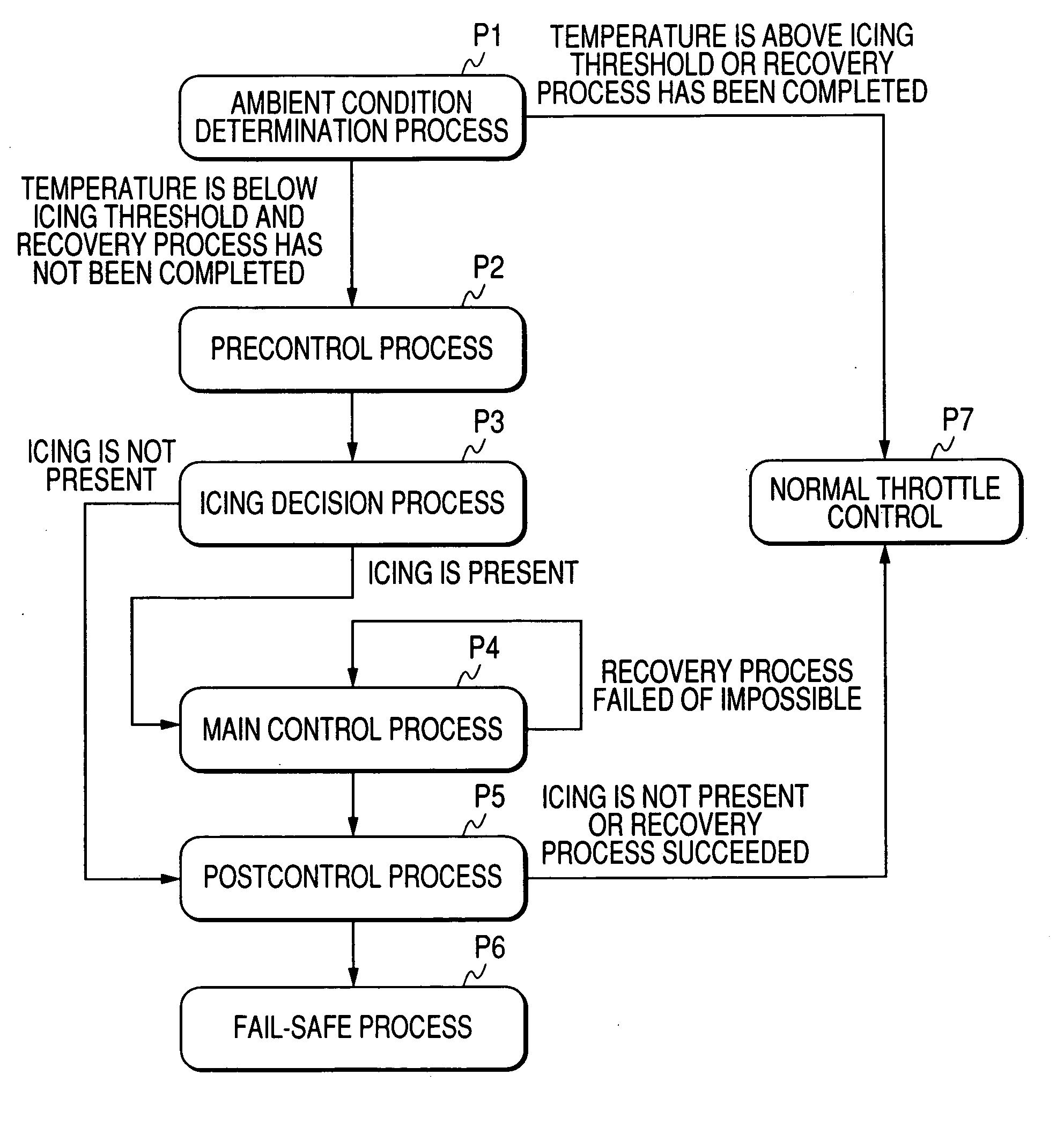
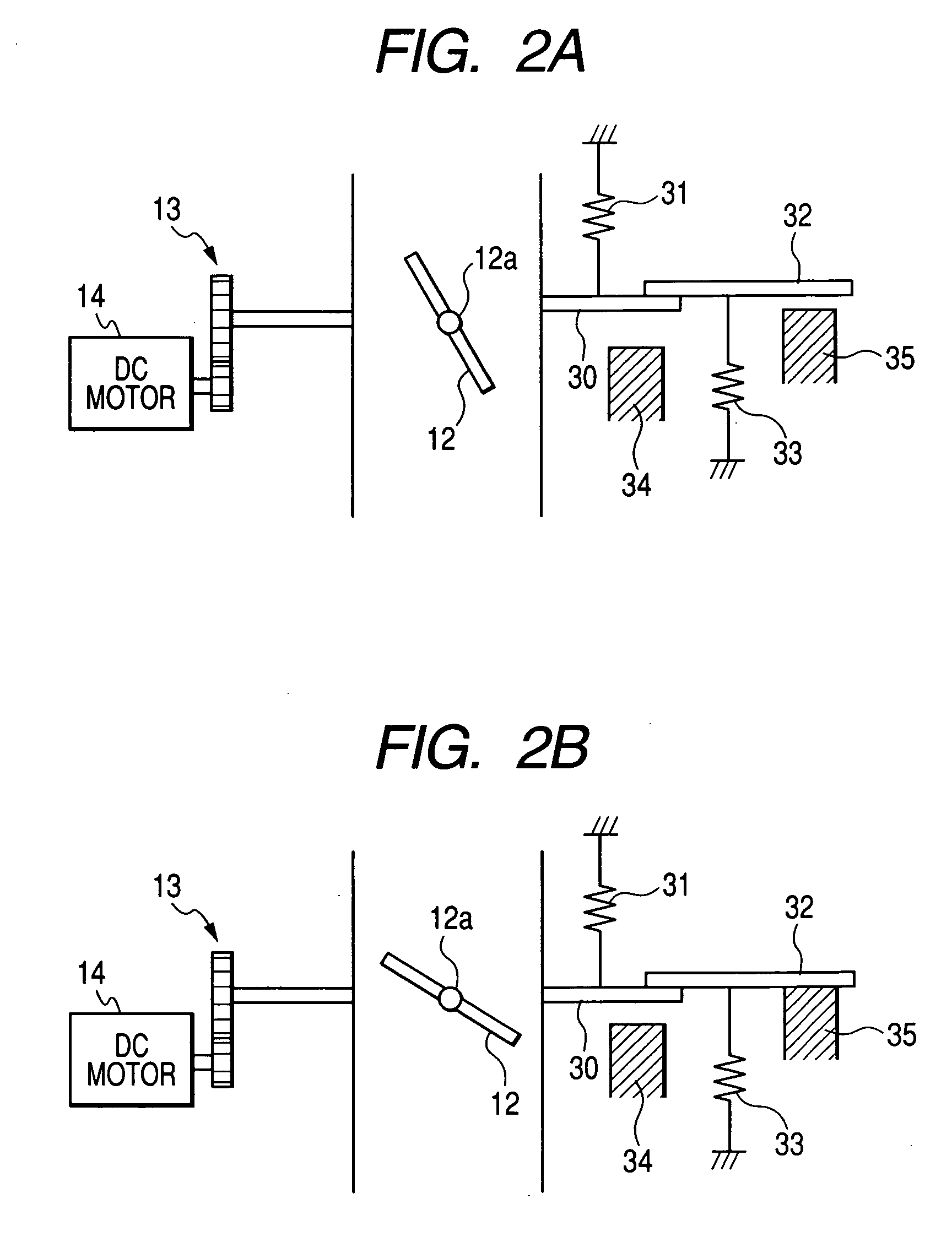
[0013] The electronic throttle control apparatus of the invention is configured to control the electric motor to drive the throttle valve in one of the closing direction and the opening direction of the throttle valve at least by an amount of a clearance (play) of the transmission gear device for transmitting torque from the electric motor to the throttle valve, and then in the other of the opening direction and the closing direction so that the throttle valve hits an ice piece. Since the electric motor can build up speed at least for the time period during which it rotates by the amount of the gear clearance, it becomes possible for the electric motor to apply a large drive force to the throttle valve, to thereby improve deicing capability.

Problems solved by technology

However, in a case where the ice pieces formed in the throttle valve stick to an inner surface of an air inlet pipe at a binding force larger than a throttle valve driving force of an electric motor, there is a possibility that the throttle valve cannot recover from the frozen state thereof, that is, the ice pieces cannot be removed from the throttle valve even if the target opening degree of the throttle valve is oscillated during the engine starting period.

Method used


Image

  • Electronic throttle control apparatus
  • Electronic throttle control apparatus
  • Electronic throttle control apparatus

Examples


Embodiment Construction

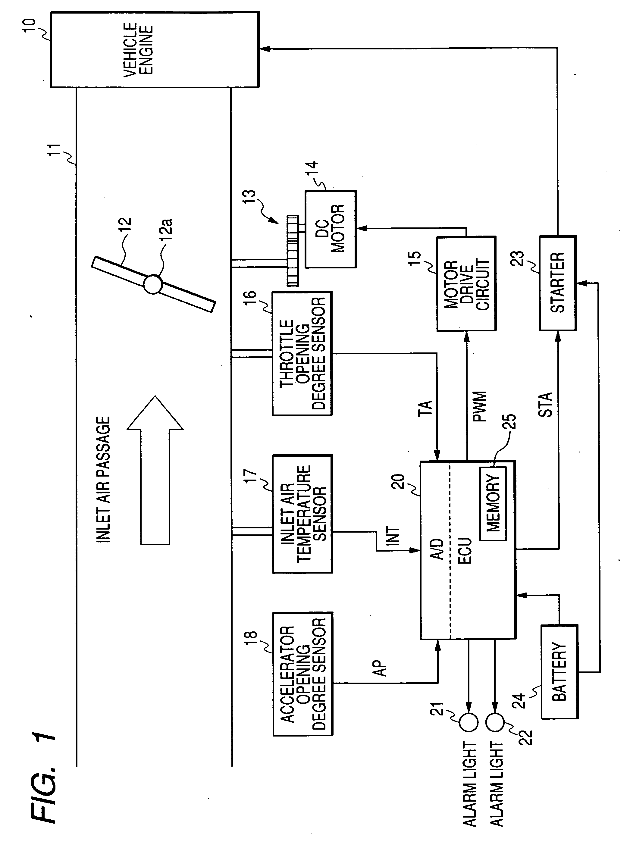
[0031]FIG. 1 is a diagram showing a structure of an electronic throttle control apparatus 100 for use in a vehicle according to an embodiment of the invention. The electronic throttle control apparatus 100 includes throttle valve ECU (Electronic Control Unit) 20, an accelerator opening degree sensor 18, an inlet air temperature sensor 17, a throttle opening degree sensor 16, a speed reduction device 13, a DC motor 14, a motor drive circuit 15, a first alarm light 21, and a second alarm light 22.

[0032] As shown in FIG. 1, an air inlet pipe 11 of an internal combustion engine (vehicle engine) 10 is provided with a throttle valve 12 for adjusting a flow volume of inlet air sucked into the engine 10. Although not shown in this figure, an air cleaner and an air flow meter are disposed upstream of the air inlet pipe 11.

[0033] A pivot 12a of the throttle valve 12 is coupled to the DC motor 14 serving as a throttle actuator through the speed reduction device 13 constituted by gears. The o...


PUM


Abstract

The electronic throttle control apparatus for a vehicle engine includes a throttle actuator including an electric motor generating torque for driving a throttle valve in an opening direction and a closing direction of the throttle valve through a transmission gear device a throttle opening degree sensor detecting an opening degree of the throttle valve, and a throttle control unit controlling the electric motor such that opening degree of the throttle valve detected by the throttle opening degree sensor becomes equal to a target throttle opening degree. The throttle control unit includes an icing decision function deciding whether or not the throttle valve is in a frozen state where icing is present in the throttle valve, and a deicing control function executing a freeze recovery process for recovering, when the throttle valve is decided to be in the frozen state by the icing decision function, the throttle valve from the frozen state by controlling the electric motor to drive the throttle valve in one of the closing direction and the opening direction at least by an amount of a clearance of the transmission gear device, and then in the other of the opening direction and the closing direction.

Description

CROSS-REFERENCE TO RELATED APPLICATION [0001] This application is related to Japanese Patent Application No. 2005-064404 filed on Mar. 8, 2005, the contents of which are hereby incorporated by reference. BACKGROUND OF THE INVENTION [0002] 1. Field of the Invention [0003] The present invention relates to an electronic throttle control apparatus for controlling an opening degree of a throttle valve by driving, through an electric motor, the throttle valve located in an air inlet passage of an internal combustion engine of a vehicle. [0004] 2. Description of Related Art [0005] There is known, as disclosed in Japanese Patent Application Laid-open No. 2000-320348, a throttle control apparatus having a configuration in which a target opening degree of a throttle valve is oscillated within a certain angular range that does not affect starting characteristic of an engine during its starting period before the engine begins complete explosion, if there is a possibility that ice pieces have be...

Claims


Application Information

Patent Timeline
IPC IPC(8): F02D11/10
CPCF02D37/02F02D41/107Y10T477/80F02D2041/228F02D2200/0404F02D2041/2027
Inventor MIYACHI, KAZUTAKA
Owner DENSO CORP
Learn More