Piezoelectric element and method for manufacturing the same, ink jet recording head and ink jet printer

a technology of piezoelectric elements and manufacturing methods, which is applied in the selection of device materials, inking apparatus, generators/motors, etc., can solve the problems of complex process and inability to be stable, and achieve good piezoelectric characteristics

Inactive Publication Date: 2006-09-28
SEIKO EPSON CORP
View PDF5 Cites 33 Cited by
  • Summary
  • Abstract
  • Description
  • Claims
  • Application Information

AI Technical Summary

Benefits of technology

[0007] In accordance with an advantage of some aspects of the invention, piezoelectric elements that can obtain good piezoelectric characteristics and methods for manufacturing such piezoelectric elements can be provided. In accordance with another aspect of some aspects of the invention, ink jet recording heads and ink jet printers that use the piezoelectric elements described above are provided.

Problems solved by technology

However, according to this method, the process for manufacturing an ink jet recording head may become complex.
However, for example, if the layer containing nickel is not formed, crystals of lanthanum nickelate oriented to (110) may be generated and mixed in the lanthanum nickelate layer, which is not stable.

Method used


Image

  • Piezoelectric element and method for manufacturing the same, ink jet recording head and ink jet printer
  • Piezoelectric element and method for manufacturing the same, ink jet recording head and ink jet printer
  • Piezoelectric element and method for manufacturing the same, ink jet recording head and ink jet printer

Examples


first embodiment

1. First Embodiment

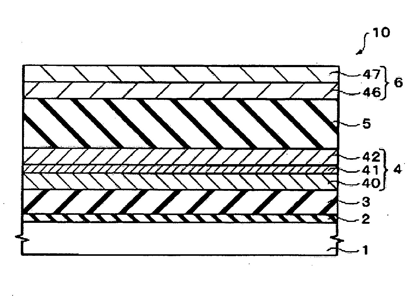
[0039] 1-1. First, a piezoelectric element 10 in accordance with a first embodiment is described.

[0040]FIG. 1 and FIG. 2 are cross-sectional views of the piezoelectric element 10, respectively. The piezoelectric element 10 includes a substrate 1, a stopper layer 2 formed on the substrate 1, a hard layer 3, formed on the stopper layer 2, a first electrode 4 formed on the hard layer 3, a piezoelectric layer 5 formed on the first electrode 4, and a second electrode 6 formed on the piezoelectric layer 5.

[0041] For example, a silicon substrate with a (110) orientation may be used as the substrate 1. For example, a layer of silicon oxide may be used as the stopper layer 2. The stopper layer 2 can function as an etching stopper, for example, in the step of etching the substrate 1 from its back surface side for forming a cavity 521 of an ink jet recording head 50 (see FIG. 7). Also, the stopper layer 2 and the hard layer 3 function as an elastic layer 55 in the ink-jet ...

second embodiment

2. Second Embodiment

[0078] 2-1. Next, an ink jet recording head in accordance with an embodiment having a piezoelectric element 10 of the first embodiment is described. FIG. 7 is a side cross-sectional view schematically showing a structure of an ink jet recording head in accordance with the present embodiment, and FIG. 8 is an exploded perspective view of the ink jet recording head. It is noted that FIG. 8 shows the ink jet recording head upside down with respect to a state in which it is normally used.

[0079] The ink jet recording head (hereafter also referred to as the “head”) 50 is equipped with a head main body 57 and piezoelectric sections 54 provided above the head main body 57, as shown in FIG. 7. It is noted that each of the piezoelectric sections 54 shown in FIG. 7 corresponds to a section having the first electrode 4, the piezoelectric layer 5 and the second electrode 6 of the piezoelectric element 10 in accordance with the first embodiment.

[0080] Also, the stopper layer...

third embodiment

3. Third Embodiment

[0103] 3-1. Next, an ink jet printer in accordance with an embodiment of the invention equipped with an ink jet recording head 50 of the second embodiment is described. FIG. 11 is a view schematically showing a structure of an ink jet printer 600 in accordance with the present embodiment. The ink jet printer 600 can function as a printer capable of printing on paper or the like. It is noted that, an upper side in FIG. 11 refers to an “upper section” and a lower side therein refers to a “lower section” in the following descriptions.

[0104] The ink jet printer 600 is equipped with an apparatus main body 620, a tray 621 for holding recording paper P in an upper rear section thereof, a discharge port 622 for discharging the recording paper P to a lower front section thereof, and an operation panel 670 on an upper surface thereof.

[0105] The apparatus main body 620 is provided on its interior mainly with a printing device 640 having a head unit 630 that can be reciproc...


PUM

PropertyMeasurementUnit
temperatureaaaaaaaaaa
thickaaaaaaaaaa

Abstract

A method for manufacturing a piezoelectric element includes the steps of forming a first electrode above a substrate, forming, above the first electrode, a piezoelectric layer composed of a piezoelectric material having a perovskite structure, and forming a second electrode above the piezoelectric layer, wherein the step of forming the first electrode includes forming a layer containing nickel, and forming, above the layer containing nickel, a lanthanum nickelate layer that is oriented to a cubic (100).

Description

[0001] The entire disclosure of Japanese Patent Application No. 2005-089166, filed Mar. 25, 2005 is expressly incorporated by reference herein. BACKGROUND [0002] 1. Technical Field [0003] The present invention relates to piezoelectric elements and methods for manufacturing the same, ink jet recording heads and ink jet printers. [0004] 2. Related Art [0005] Ink jet printers are known as printers that can realize high image quality and high speed printing. In order to improve the characteristics of piezoelectric elements in ink jet recording heads for ink jet printers, it is important to control the crystal orientation of the piezoelectric layers. [0006] As a method to control the crystal orientation, Japanese Laid-open patent application JP-A-2000-158648 describes a control method using a MgO (100) single crystal substrate. However, according to this method, the process for manufacturing an ink jet recording head may become complex. SUMMARY [0007] In accordance with an advantage of s...

Claims


Application Information

Patent Timeline
Patent Type & Authority Applications(United States)
IPC IPC(8): H01L41/047B41J2/055B41J2/045B41J2/135B41J2/14B41J2/145B41J2/16H01L41/09H01L41/18H01L41/187H01L41/22H01L41/29H01L41/319
CPCB41J2/14233B41J2/161B41J2/1623B41J2/1629B41J2/1642B41J2/1646Y10T29/42H01L41/0478H01L41/29H01L41/319Y10T29/49128Y10T29/49155B41J2202/03H10N30/878H10N30/06H10N30/079
Inventor IWASHITA, SETSUYAOHASHI, KOJIHIGUCHI, TAKAMITSU
Owner SEIKO EPSON CORP
Why Eureka
Try Eureka