Stress birefringence compensation in polarizing beamsplitters and systems using same

a beam splitter and birefringence technology, applied in the field of optical systems, can solve the problems of dramatic contrast reduction, increase in the brightness in the dark state, and reduction in contrast, and achieve the effect of maximizing the compensation for birefringen

Active Publication Date: 2006-09-28
3M INNOVATIVE PROPERTIES CO
View PDF24 Cites 22 Cited by
  • Summary
  • Abstract
  • Description
  • Claims
  • Application Information

AI Technical Summary

Benefits of technology

[0006] One embodiment of the invention is directed to an optical unit that comprises a polarizing beamsplitter (PBS). The PBS has a first cover having a first surface and a second surface for transmitting a light beam and a second cover having at least a first surface for transmitting a light beam. The second cover is arranged with its first surface opposing the first surface of the first cover. A reflective polarizing layer is disposed between the first surfaces of the first and second covers. A quarter-wave retarding element is disposed proximate the second surface of the first cover. The quarter-wave retarding element is aligned substantially to maximize compensation for birefringence of the first cover for light that is double-passed through the first cover, between the first and second surfaces.

Problems solved by technology

This causes leakage of light after reflection from the imager panel, resulting in an increase in the level of brightness in the dark state and, therefore, a reduction in the contrast.
In addition, if hardware to mount an imaging device is attached to the input prism of a PBS, this will usually result in dramatic contrast reductions, over at least some regions of the PBS, due to resulting stresses in the glass.
These low SOC glasses are, therefore, not environmentally desirable materials and are also expensive and difficult to process.
Additionally, the low SOC glasses have a high refractive index, in excess of 1.8, which may lead to optical inefficiencies or aberrations when matching to the lower refractive index polarizing layers.

Method used


Image

  • Stress birefringence compensation in polarizing beamsplitters and systems using same
  • Stress birefringence compensation in polarizing beamsplitters and systems using same
  • Stress birefringence compensation in polarizing beamsplitters and systems using same

Examples


Embodiment Construction

[0026] The present invention is applicable to systems that use polarizing beamsplitters (PBSs), and is believed to be particularly useful for image projection systems that incorporate PBSs for separating image light generated using a polarization modulator from illumination light. While the invention may be useful in any application where a PBS is used, it is described below particularly as used in projection systems. The scope of the invention is not intended to be limited to only projection systems.

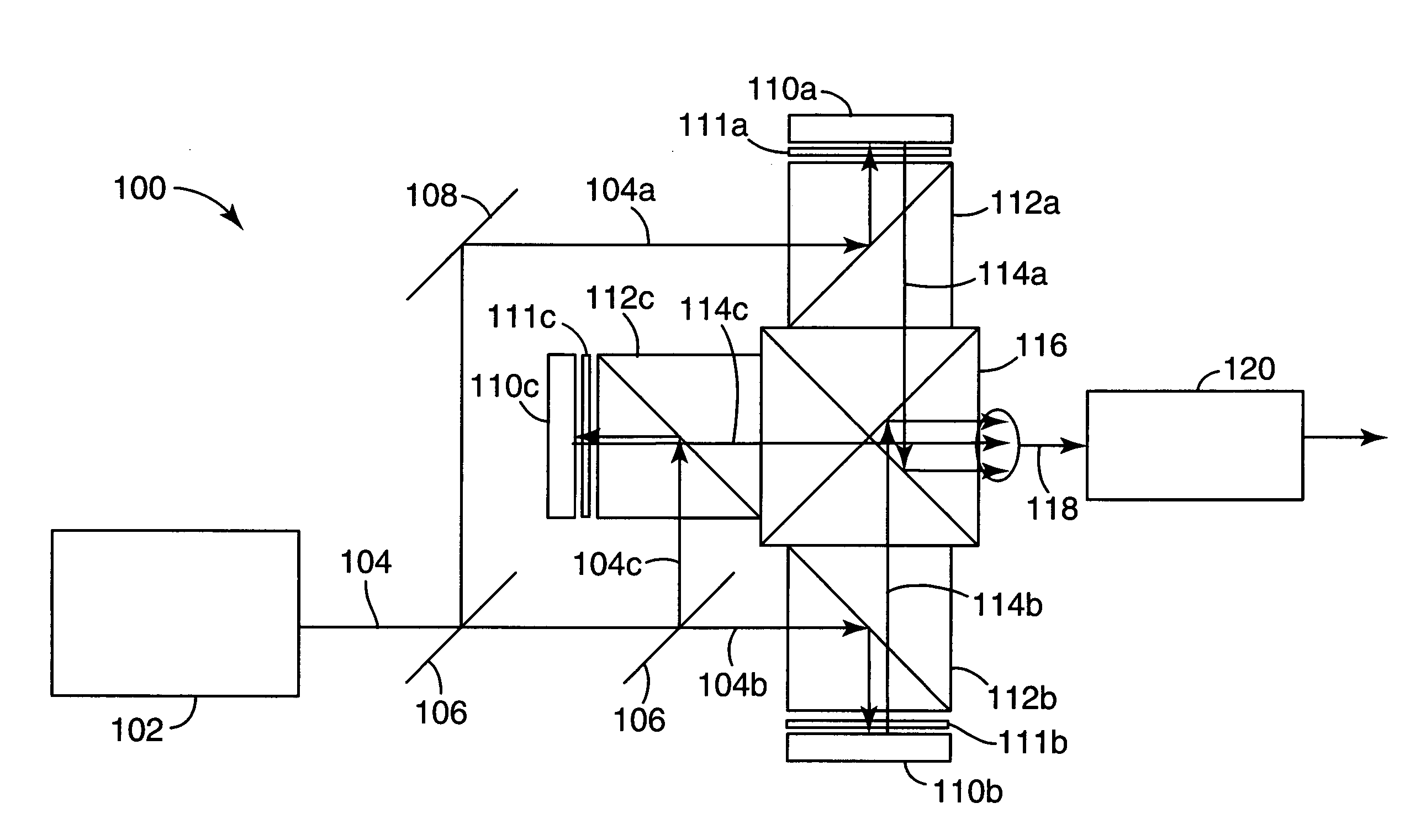
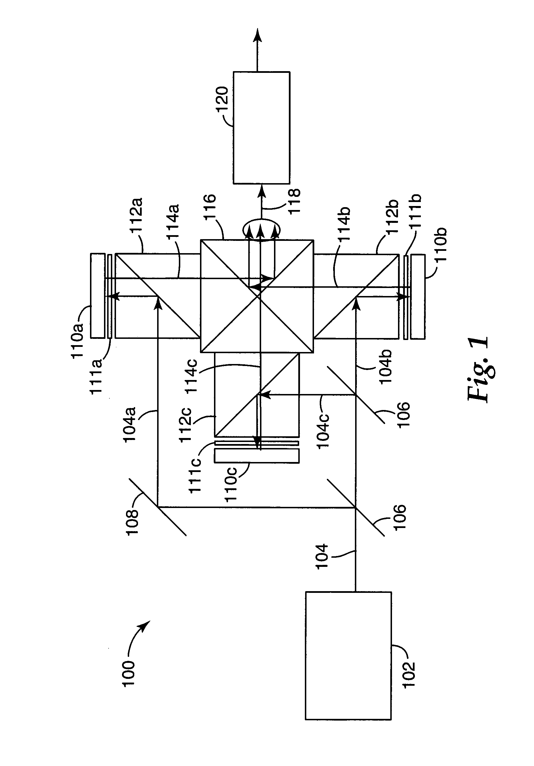
[0027] The invention may be used in many different types of projection system. One exemplary embodiment of a multi-panel projection system 100 that may incorporate the invention described below is schematically illustrated in FIG. 1. The projection system 100 is a three-panel projection system, having a light source 102 that generates a light beam 104, containing light in three different color bands. The light beam 104 is split by color splitting elements 106 for example, dichroic mirr...


PUM


Abstract

Some projection systems use a polarization beamsplitter (PBS) for coupling light to and from an image-forming device. The PBS is typically formed with a reflective polarizing layer disposed between glass covers. Stress birefringence in the glass cover lying between the reflective polarizing layer and the image-forming device can reduce the image contrast of the projection system. A quarter-wave retarding element positioned between the glass cover and the image-forming device is used to compensate for the birefringence, at least in part. This permits the PBS to use glass covers formed of a glass material having a higher stress optic coefficient than before, while still maintaining high image contrast.

Description

FIELD OF THE INVENTION [0001] The invention relates to optical systems and more particularly to the optical systems that use polarizing beamsplitters for separating or combining light beams in different polarization states. BACKGROUND [0002] The function of a polarizing beamsplitter (PBS) is to reflect light in one polarization state and to transmit light in the orthogonal polarization state. Consequently, PBSs find widespread use in optical systems that rely on the polarization of the light. An example of one such system is an image projection system that uses a reflective liquid crystal display (LCD) panel for modulating an illumination light beam: a polarized illumination light beam is directed to the LCD panel, for example by reflection in the PBS. The light beam is spatially modulated by the LCD panel so that the reflected beam contains some unmodulated light in the polarization state of the illumination beam and some modulated light in the orthogonal polarization state. The un...

Claims


Application Information

Patent Timeline
Patent Type & Authority Applications(United States)
IPC IPC(8): G03B21/14
CPCG02B27/1026G02B27/145G02B27/149G02B27/283H04N9/3105H04N9/315G02B5/30G02B27/10
Inventor AASTUEN, DAVID J.W.BRUZZONE, CHARLES L.MA, JIAYING
Owner 3M INNOVATIVE PROPERTIES CO
Why Eureka
Try Eureka