
System and process for robust sound source localization

a sound source and localization system technology, applied in the field of finding the location of a sound source, can solve the problems of wasting useful information, not fully taking advantage of the weighting function of research into the direct approach, and more computationally expensive than the 2-tdoa method, so as to maximize the energy of each sensor, enhance the robustness of the selected location, and mitigate the effect of uncorrelated noise and/or reverberation

Inactive Publication Date: 2006-09-28
MICROSOFT TECH LICENSING LLC
View PDF4 Cites 3 Cited by
  • Summary
  • Abstract
  • Description
  • Claims
  • Application Information

AI Technical Summary

Benefits of technology

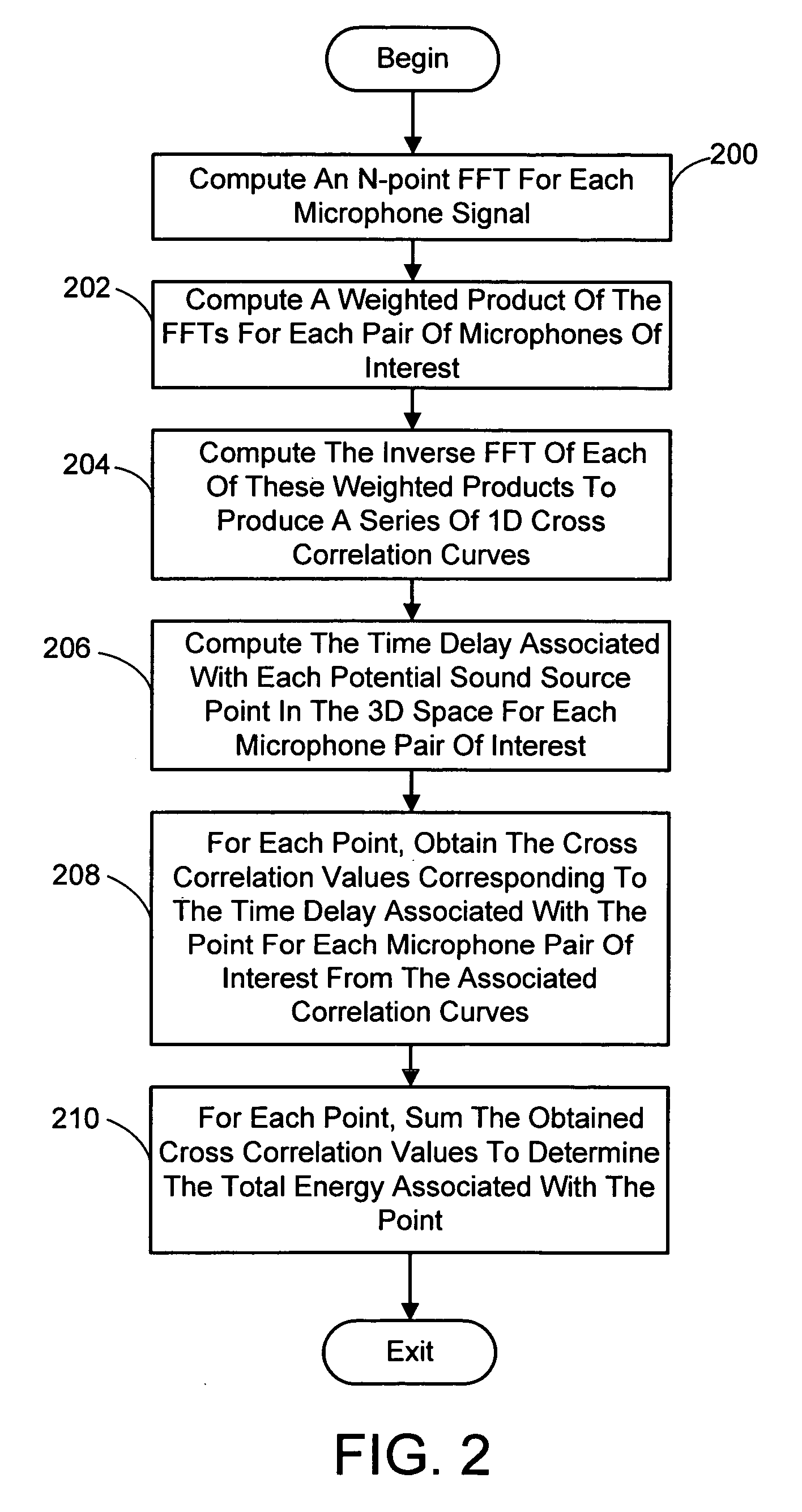
[0012] As for the SB SSL approach, this also generally involves first inputting the signal generated by each audio sensor of the aforementioned microphone array. Then, the location of the sound source is selected as the location that maximizes the energy of each sensor of the microphone array. The input signals are again weighted using a weighting function that enhances the robustness of the selected location by mitigating the effect of uncorrelated noise and / or reverberation. In tested versions of the system and process the energy is computed in FFT domain. However, in general, the energy can be computed in any domain, e.g., FFT, MCLT (modulated complex lapped transforms), or time domains.

Problems solved by technology

The disadvantage is that it makes a premature decision on an intermediate TDOA in the first step, thus throwing away useful information.
While preserving intermediate data, this latter approach does have the disadvantage that it can be more computationally expensive than the 2-TDOA methods.
Even so, research into the direct approach has not yet taken full advantage of the aforementioned weighting functions.
However, they differ in theoretical merits and computational complexity.

Method used


Image

  • System and process for robust sound source localization
  • System and process for robust sound source localization
  • System and process for robust sound source localization

Examples


experiment 2

4.3. SB SSL

[0076] The comparison between the proposed new SB approach against existing SB approaches is summarized in Table 2 as shown in FIG. 6.

4.4. Experiment 3: 2-TDOA vs. 1-TDOA vs. SB

[0077] The comparison between the proposed new 1-TDOA and SB approaches against an existing 2-TDOA approach is summarized in Table 3 shown in FIG. 7. The 2-TDOA approach we used is the maximum likelihood estimator JTDOA developed in [2], which is one of the best 2-TDOA algorithms. In addition to using Tests R and S, we further use Test A to see how they perform with respect to different source locations. The result is summarized in Table 4 shown in FIG. 8.

4.5. Observations

[0078] The following observations can be made based on Tables 1-4:

[0079] From Table 1, the proposed new 1-TDOA outperforms the PHAT and ML based approaches. The PHAT approach works quite well in general, but performs poorly when the SNR is low. Tele-conferencing systems, e.g., [4], require prompt SSL, and the promptness of...


PUM


Abstract

A system and process for finding the location of a sound source using direct approaches having weighting factors that mitigate the effect of both correlated and reverberation noise is presented. When more than two microphones are used, the traditional time-delay-of-arrival (TDOA) based sound source localization (SSL) approach involves two steps. The first step computes TDOA for each microphone pair, and the second step combines these estimates. This two-step process discards relevant information in the first step, thus degrading the SSL accuracy and robustness. In the present invention, direct, one-step, approaches are employed. Namely, a one-step TDOA SSL approach and a steered beam (SB) SSL approach are employed. Each of these approaches provides an accuracy and robustness not available with the traditional two-step approaches.

Description

BACKGROUND [0001] 1. Technical Field [0002] The invention is related to finding the location of a sound source, and more particularly to a multi-microphone, sound source localization system and process that employs direct approaches utilizing weighting factors that mitigate the effect of both correlated and reverberation noise. [0003] 2. Background Art [0004] Using microphone arrays to do sound source localization (SSL) has been an active research topic since the early 1990's [2]. It has many important applications including video conferencing [1],[4],[7], surveillance, and speech recognition. There exist various approaches to SSL in the literature. So far, the most studied and widely used technique is the time delay of arrival (TDOA) based approach [2],[7],[8]. [0005] When using more than two microphones, the conventional TDOA SSL is a two-step process (referred to as 2-TDOA hereinafter). In the first step, the TDOA (or equivalently the bearing angle) is estimated for each pair of ...

Claims


Application Information

Patent Timeline
Patent Type & Authority Applications(United States)
IPC IPC(8): H04R3/00G10L21/02
CPCG10L21/0272G10L2021/02165H04R3/005
Inventor RUI, YONGFLORENCIO, DINEI A.
Owner MICROSOFT TECH LICENSING LLC
Learn More