
Self-configurable resonance antenna

a resonance antenna and self-configurable technology, applied in the direction of antennas, antenna details, elongated active element feed, etc., can solve the problems of small packaging of state-of-the-art communications devices such as personal communications handsets, insufficient space for conventional quarter and half wavelength antenna elements, and designers struggling to obtain adequate multi-band antenna performance for the multi-band features of devices, efficiency or bandwidth

Active Publication Date: 2015-04-30
AAC TECH PTE LTD
View PDF3 Cites 6 Cited by
  • Summary
  • Abstract
  • Description
  • Claims
  • Application Information

AI Technical Summary

Benefits of technology

The patent text explains that an effective antenna for communication devices needs to have a minimum size of a half wavelength of the operating frequency to maximize energy transmitted or received. This is because a quarter-wavelength antenna operable above a ground plane has properties similar to a half-wavelength antenna. The text also mentions that it is preferable for an antenna to be efficient, meaning it should be able to work over a wide range of frequencies or in multiple modes. This would make it easier to design a communication device that can transmit and receive signals in different ways.

Problems solved by technology

Smaller packaging of state-of-the-art communications devices, such as personal communications handsets, does not provide sufficient space for the conventional quarter and half wavelength antenna elements.
Currently, designers struggle to obtain adequate multi-band antenna performance for the multi-band features of the devices.
But as is known, efficiency and bandwidth are related and a design trade-off is therefore required.
Designers can optimize performance in one (or in some cases more than one) operating frequency band, but usually must compromises the efficiency or bandwidth to achieve adequate performance in two or more bands simultaneously.
However, most portable communications devices seldom require operation in more than one band.

Method used


Image

  • Self-configurable resonance antenna
  • Self-configurable resonance antenna
  • Self-configurable resonance antenna

Examples


Embodiment Construction

[0019]Reference will now be made to describe the exemplary embodiments of the present disclosure in detail.

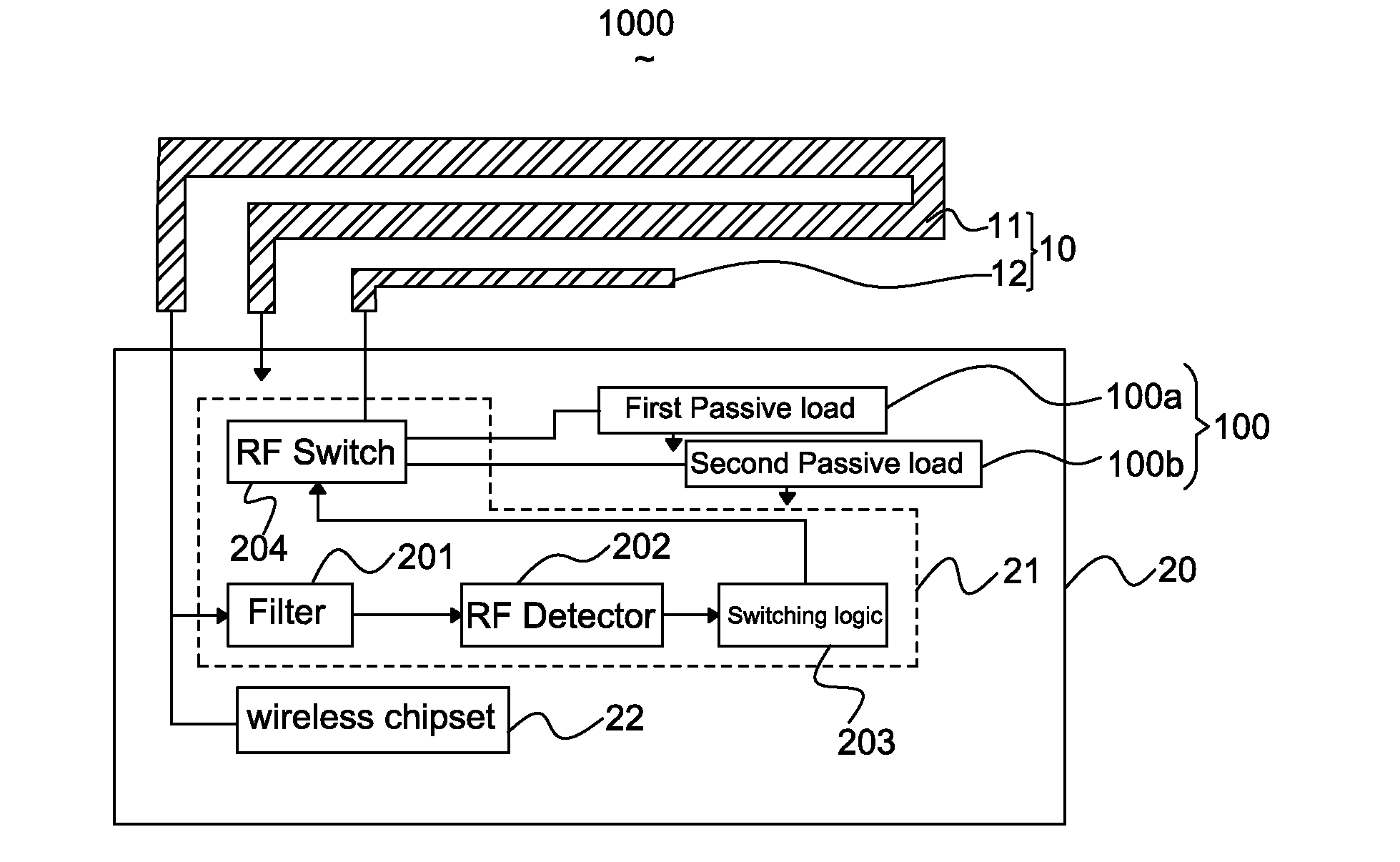
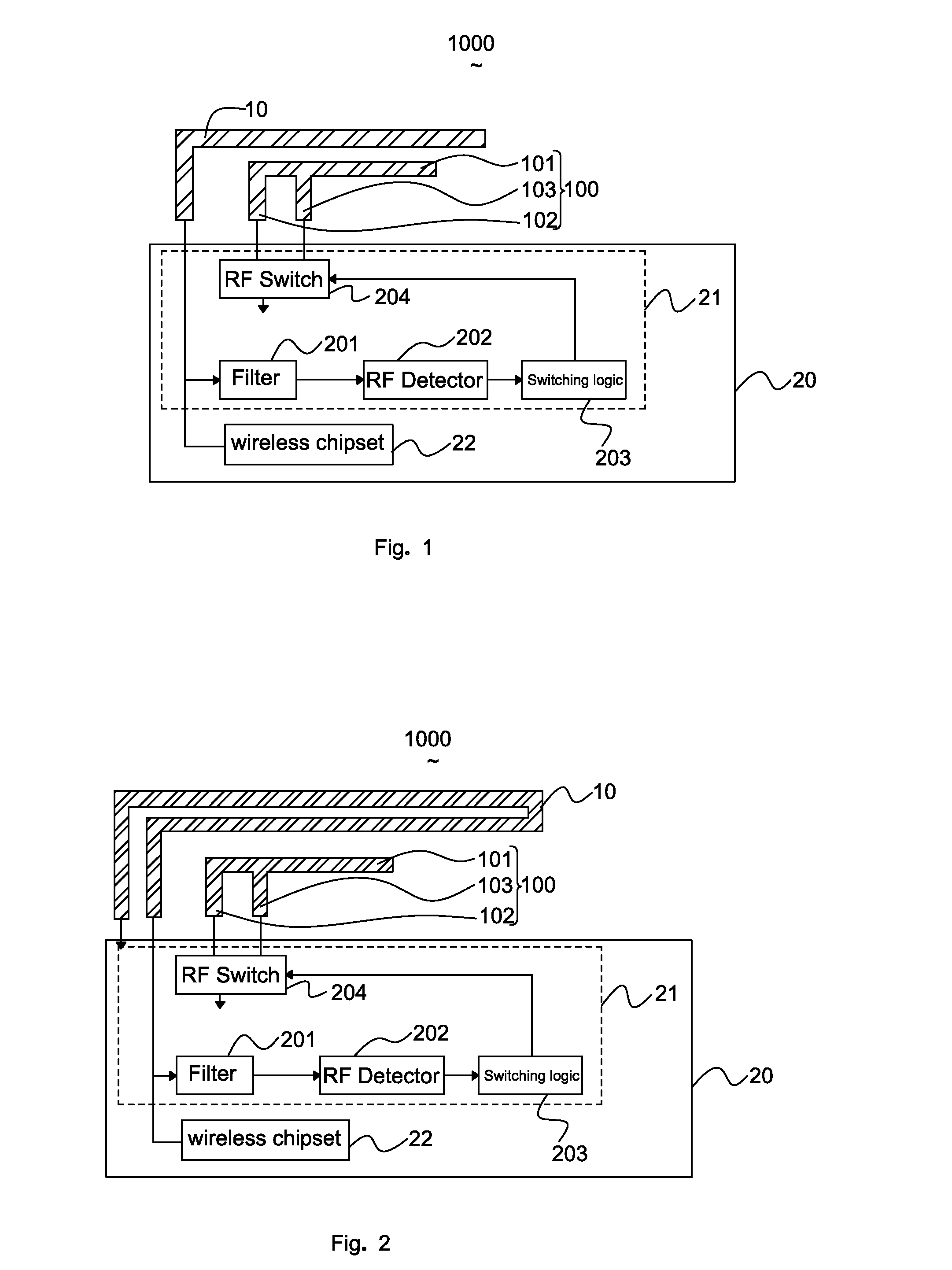
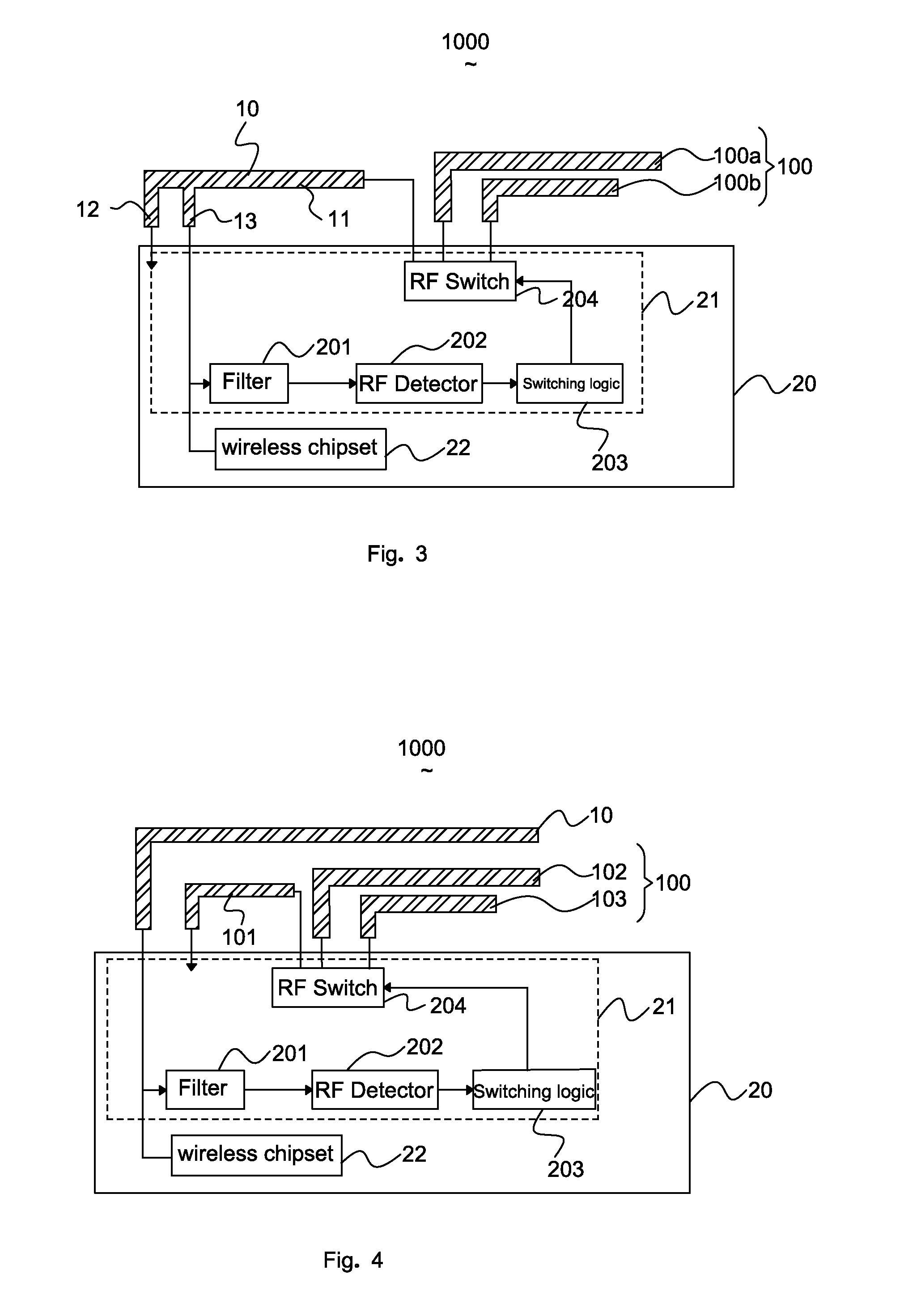
[0020]Referring to FIG. 1, a schematic view of a self-configurable resonance antenna used in a handheld (i.e., mobile phones, PDA, panel computers or mobile powers) according to a first exemplary embodiment of the present disclosure is shown. The handheld has a print circuit board 20 acting as a ground plane, a self-configurable resonance antenna 1000 and wireless chipset 22. The self-configurable resonance antenna 1000 will establish a connection with a base station in one frequency band through the wireless chipset 22 when the handheld is powered up. The wireless chipset 22 transmits or receives signals at the frequency band by the self-configurable resonance antenna 1000. The self-configurable resonance antenna 1000 comprises a main antenna 10 capable of operating in different frequency bands, and a coupling element 100 corresponding to the main antenna 10 capable of configu...


PUM


Abstract

A self-configurable resonance antenna includes a main antenna for transmitting and receiving radio waves of a plurality of mutually different frequency bands, a coupling element having at least two radiating patches with different effective electrical lengths for configuring the impedance of the self-configurable resonance antenna, and a matching circuit disposed between the main antenna and the coupling element. The matching circuit has a filter, a RF detector, a switching logic and a RF switch, the RF switch switching between at least the two radiating patches with different effective electrical lengths for adjusting the main antenna operating in different frequency bands.

Description

RELATED PATENT APPLICATION[0001]This application claims the priority benefit of Chinese Patent Application Filing Serial Number CN 201310518179.5, filed on Oct. 28, 2013, the disclosure of which is herein incorporated by reference in its entirety.FIELD OF THE INVENTION[0002]The present disclosure generally relates to an antennas for wireless communications devices, and more particularly to a self-configurable resonance antenna for adaptively controlling antenna parameters to improve performance of the communications device.DESCRIPTION OF RELATED ARTS[0003]With the recent advancements in wireless technology, Long Term Evolution (LTE) has become a dominant wireless communications standard. Smart phones, handheld computers, laptops and even GPS device running on high LTE speeds have made wireless communication easier than before. Since the LTE standard covers a range of many different bands, this has driven a demand for multiband antenna.[0004]It is known that antenna performance is de...

Claims


Application Information

Patent Timeline
IPC IPC(8): H01Q1/50
CPCH01Q1/50H01Q5/328H01Q1/243H01Q5/378H01Q9/42
Inventor TAY, ROGERHONG, NG GUANSAN, BONG JUNCHOON, TAN YEWGHIT, CHAN YUNLENG, KAREN GOH HUI
Owner AAC TECH PTE LTD
Learn More