Excitation device and method for downhole seismic testing using the same

a technology of seismic testing and excitation device, which is applied in the direction of seismic testing, measurement device, instruments, etc., can solve the problems of unstable target structure or the surrounding ground, change of structure, etc., and achieve the effect of convenient carriage and convenient disassembly

Inactive Publication Date: 2013-10-31
KOREA INST OF GEOSCI & MINERAL RESOURCES
View PDF5 Cites 6 Cited by
  • Summary
  • Abstract
  • Description
  • Claims
  • Application Information

AI Technical Summary

Benefits of technology

[0014]The present invention is directed to providing an excitation device for downhole seismic testing, and a method for downhole seismic testing using the same, which can be conveniently disassembled and assembled to allow convenient carriage.
[0016]The present invention is also directed to providing an excitation device for downhole seismic testing and a method for downhole seismic testing using the same, which may maximize expressed energy while securing orientation of seismic waves upon generation of the seismic waves. Here, the present invention is directed to providing test data for multiple purposes through diversification of the intensity of the expressed energy.
[0017]The present invention is also directed to providing an excitation device for downhole seismic testing and a method for downhole seismic testing using the same, which employs an existing observation hole for observing an underground water level, instead of constructing a separate test hole which requires an operation for abandoning the hole, and permits combinational analysis of quantitative distribution variation of shear wave velocity and compressional wave velocity corresponding to variation of an underground water level at the same spatial location, thereby significantly improving reliability of stability testing of target ground.

Problems solved by technology

Even in this case, however, stability of a target structure or the surrounding ground and structures can change during construction of the structure or over time due to abnormal variation of material or design factors, unpredicted inner or outer factors, and the like.
Nevertheless, periodic and continuous measurement and evaluation of the shear wave velocity for most ground materials which require stability has never been taken into consideration.

Method used


Image

  • Excitation device and method for downhole seismic testing using the same
  • Excitation device and method for downhole seismic testing using the same
  • Excitation device and method for downhole seismic testing using the same

Examples


Embodiment Construction

[0038]Exemplary embodiments of the present invention will now be described in detail with reference to the accompanying drawings.

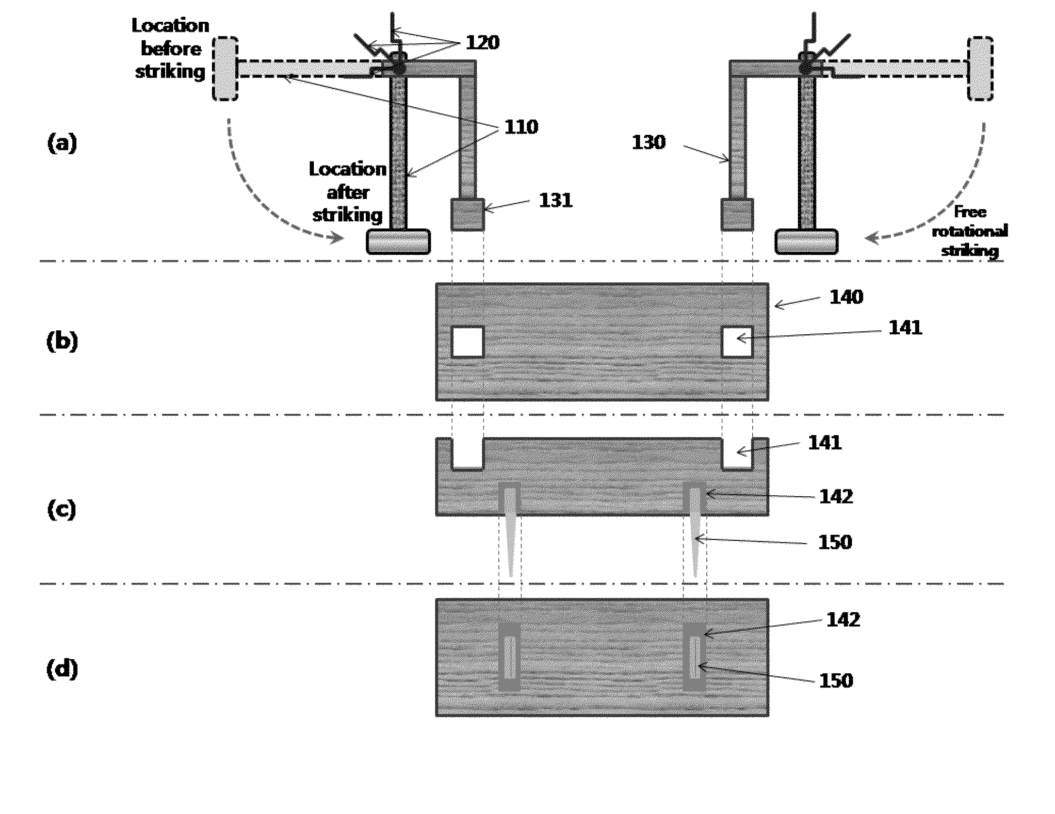
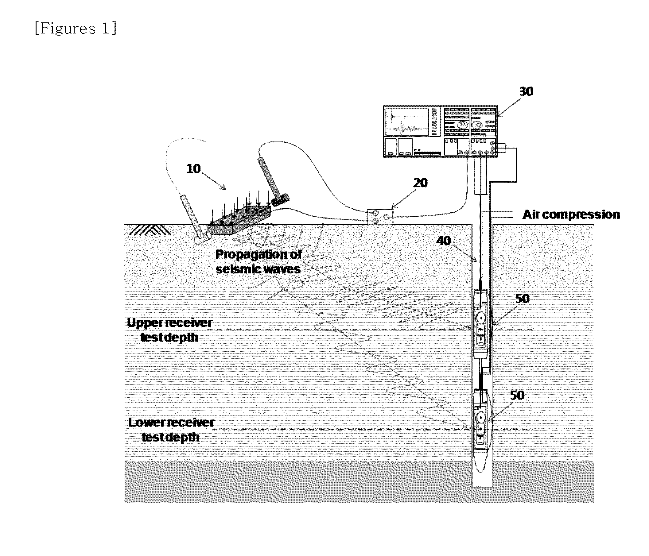
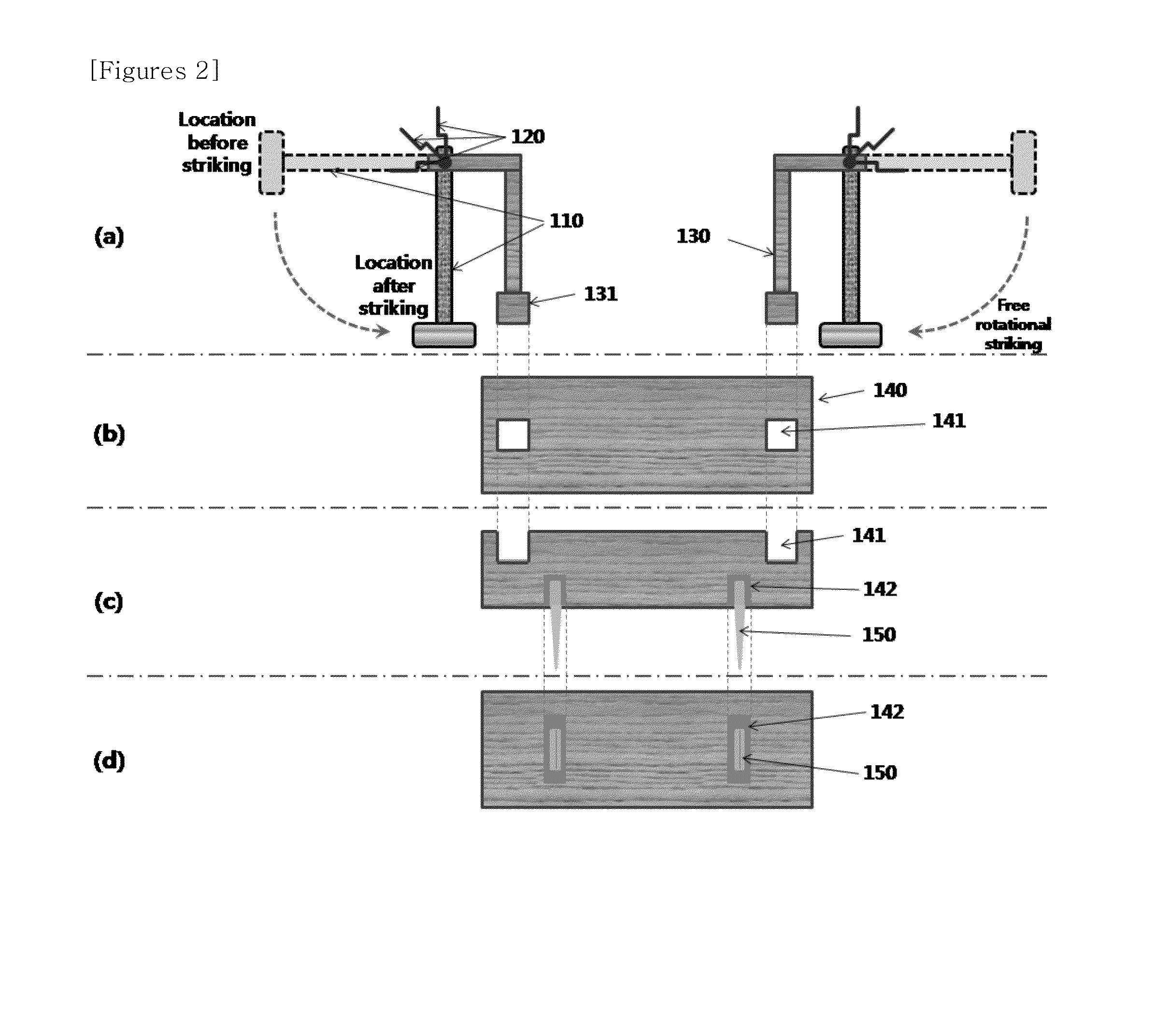
[0039]For most embankment structures, a surface layer of the crest is subjected to pavement for preventing constituent materials from suffering erosion or weathering, or to block construction for protection or performance guarantee. For the ground around an excavation site, the surface layer is also subjected to pavement or other processes using pavement blocks. For such reasons, target ground has a sub-base, a base, and surface layers, such as ascon pavement, flexible pavement, pavement blocks, and the like, formed thereon. To provide continuous stability evaluation with respect to target facilities and surround ground including ground materials, which are covered with additional materials including pavement or processing blocks, an observation hole for observing an underground water level is formed to a predetermined depth from the ground surface at an e...


PUM


Abstract

An excitation device for downhole seismic testing, includes an excitation hammer, a holding arm connected at one end thereof to the excitation hammer to allow the excitation hammer to rotate about the other end thereof, a support post having the other end of the holding arm rotatably coupled to an upper end thereof to support the excitation hammer and the holding arm at a certain height, and an excitation source configured to allow the support post to stand upright on the upper side thereof and which generates a seismic wave when struck by the rotated excitation hammer. The support post is formed at a lower end thereof with a securing section detachably inserted into a groove for the support post formed on the upper side of the excitation source such that the support post, the holding arm, the excitation hammer and the excitation source can be separated from each other.

Description

BACKGROUND OF THE INVENTION[0001]1. Field of the Invention[0002]The present invention relates to an excitation device and method for downhole seismic testing using the same, and more particularly, to an excitation device for downhole seismic testing, which is installed on the ground to generate seismic waves with efficiency and accuracy and allows separation into individual units for convenient carriage and secure installation, and a method for downhole seismic testing using the same.[0003]2. Description of the Related Art[0004]For efficient management of water that is essential for human life and industrial development, structures, such as dams, reservoirs, seawalls, banks, and the like, can be built not only with reinforced concrete, but also in the form of an embankment structure through construction of earth materials such as soil, sand, rock, and the like.[0005]The crest of the embankment structure constructed of the earth materials is generally paved with asphalt, concrete or ...

Claims


Application Information

Patent Timeline
Patent Type & Authority Applications(United States)
IPC IPC(8): G01V1/147
CPCG01V1/147G01N29/14
Inventor SUN, CHANG-GUK
Owner KOREA INST OF GEOSCI & MINERAL RESOURCES
Why Eureka
Try Eureka