Portable device for transferring fluids

Inactive Publication Date: 2006-09-28
MOTOR COMPONENTS
View PDF15 Cites 3 Cited by
  • Summary
  • Abstract
  • Description
  • Claims
  • Application Information

AI Technical Summary

Benefits of technology

[0012] It is still another object of the present invention to provide a portable device, built from light weight and readily available components, for transferring fluids.

Problems solved by technology

Unfortunately, Carter's two-cycle engine is noisy, bulky, and requires the mixing and use of an oil / gasoline fuel mixture.
The separate motor and pump increase the parts count, complexity, parts costs, assembly time, and overall manufacturing costs for the device.
Thus, Carter's pump is portable, but not easily handled.
Unfortunately, Hill uses a relatively bulky pump having a chain-driven gear pump.
Umholtz uses an on-board battery and a rotary pump driven by a motor power shaft, all of which add to the weight and bulk of the pump.
Unfortunately, for both Hill and Umholtz, the separate motor and pump increase the parts count, complexity, parts costs, assembly time, and overall manufacturing costs for the device.
Unfortunately, Liu discloses a bulky configuration including a separate motor and a custom-manufactured pumping mechanism including ring and pinion gears, discs, and blocks.
Unfortunately, the separate motor and pumping mechanism increase the parts count, complexity, parts costs, assembly time, and overall manufacturing costs for the device.
Unfortunately, the separate motor and pumping arrangement increase the parts count, complexity, parts costs, assembly time, and overall manufacturing costs for the device.
Further, the separate motor and pump and the gear train increase the weight and bulk of the pump.
Unfortunately, Clarke and Sciortino use an AC powered pump, limiting the situations in which the pumps can be used, and include a relatively large housing.
Unfortunately, Beny and Sheya disclose the rather narrow application of a pump mounted to a bottle.

Method used


Image

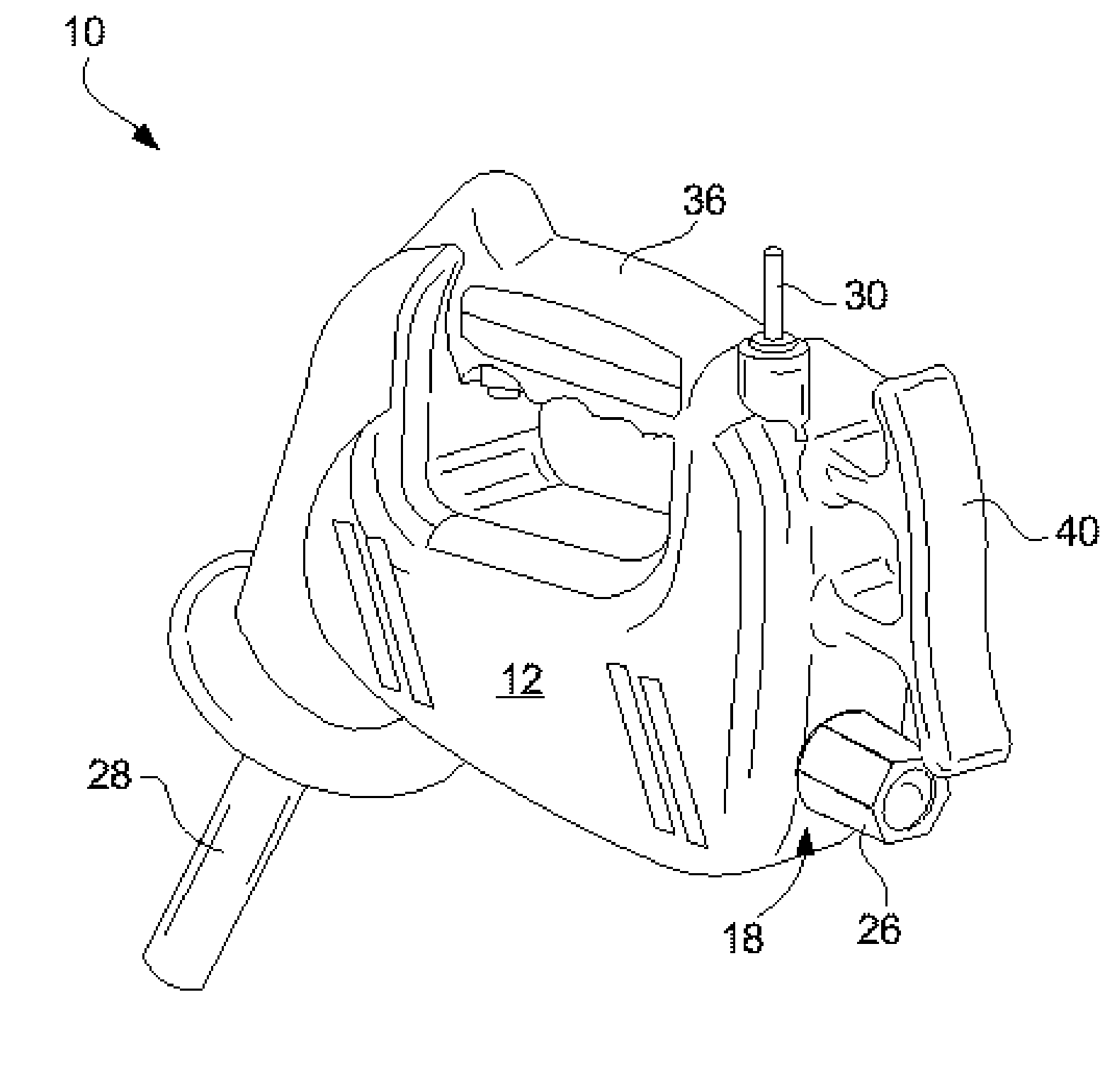
  • Portable device for transferring fluids
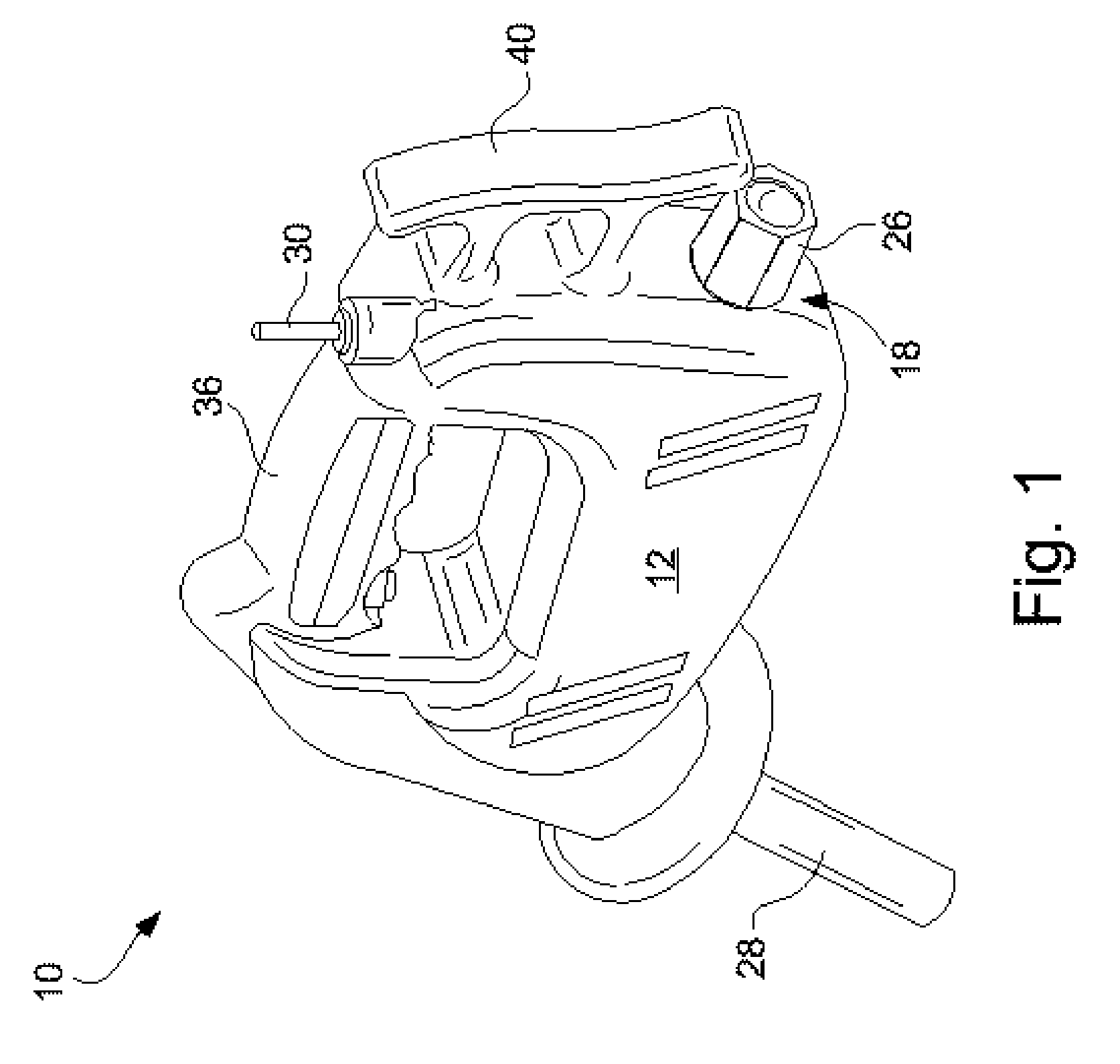
  • Portable device for transferring fluids
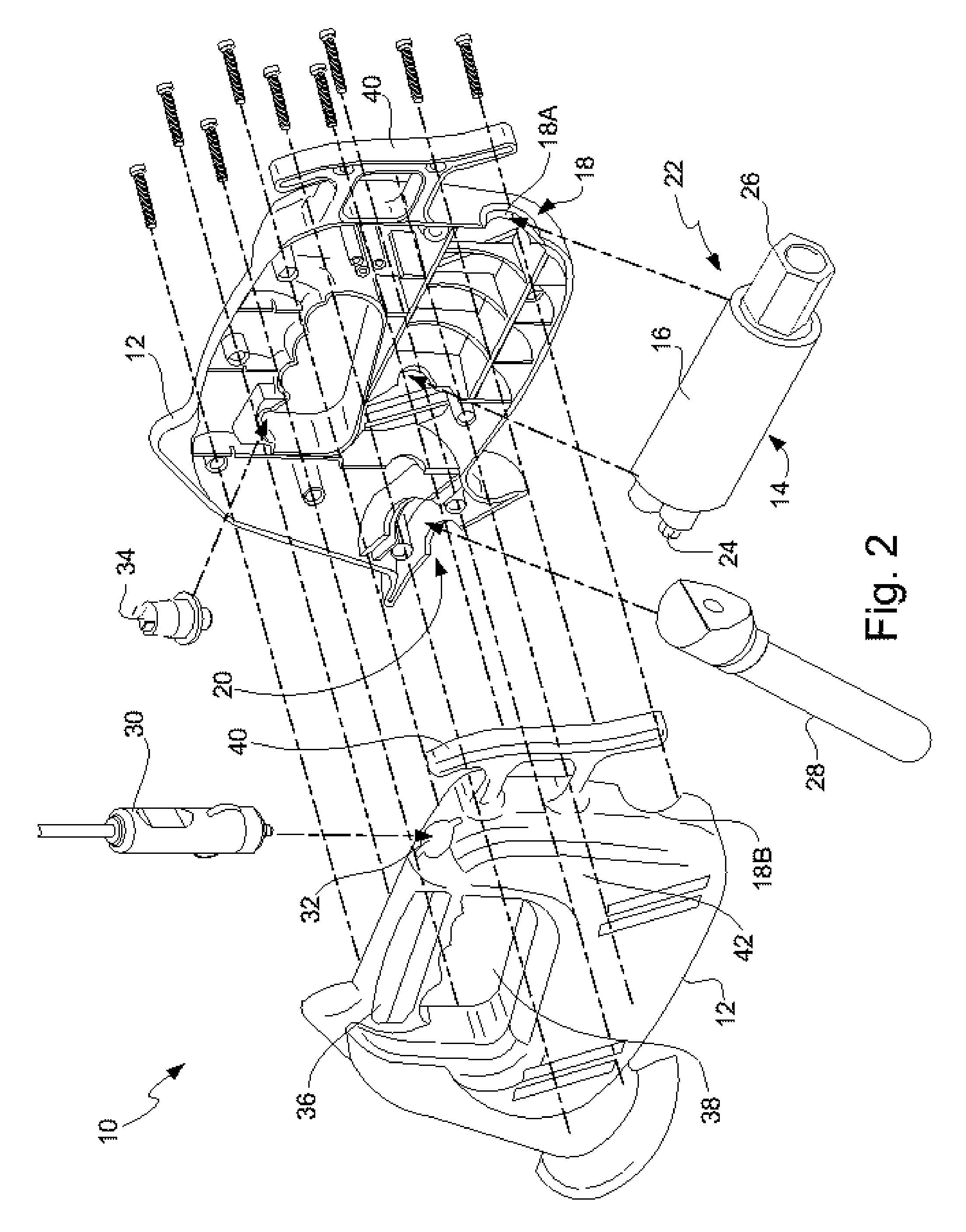
  • Portable device for transferring fluids

Examples


Embodiment Construction

[0018] At the outset, it should be appreciated that like drawing numbers on different drawing views identify identical, or functionally similar, structural elements of the invention. While the present invention is described with respect to what is presently considered to be the preferred aspects, it is to be understood that the invention as claimed is not limited to the disclosed aspects.

[0019] Furthermore, it is understood that this invention is not limited to the particular methodology, materials and modifications described and as such may, of course, vary. It is also understood that the terminology used herein is for the purpose of describing particular aspects only, and is not intended to limit the scope of the present invention, which is limited only by the appended claims.

[0020] Unless defined otherwise, all technical and scientific terms used herein have the same meaning as commonly understood to one of ordinary skill in the art to which this invention belongs. Although any...


PUM


Abstract

The invention broadly comprises a portable device for transferring fluids. The device includes an external housing with an inlet and a discharge and a pump disposed within the external housing. The pump includes a pump housing, a motor, and a pumping means. The motor and the pumping means are disposed within the pump housing and the pump comprises an inlet port and an outlet port cooperatively engaged with the inlet and the discharge, respectively. The device also includes a control switch connected to the pump and a power cord with a first end operatively connected to the switch and a second end comprising a power adapter. The power adapter can be a DC power source adapter or a line voltage adapter. In some aspects, the DC power source adapter is configured to connect to a power port adapter in an automotive vehicle.

Description

FIELD OF THE INVENTION [0001] The invention relates generally to portable transfer pumps. In particular, the invention relates to a portable transfer pump for transferring fuels, having an in-line motor and an ergonomic shape. Further, the invention relates to a portable transfer pump powered by an adapter in an automotive vehicle. BACKGROUND OF THE INVENTION [0002] It is known to use portable pumps to transfer fluids. For example, U.S. Pat. No. 6,132,178 (Carter) discloses a hand-held pump device that can be used for transferring fluids. Carter discloses a two-cycle, air-cooled engine with a power shaft connected to a pump, specifically a water pump. Unfortunately, Carter's two-cycle engine is noisy, bulky, and requires the mixing and use of an oil / gasoline fuel mixture. The separate motor and pump increase the parts count, complexity, parts costs, assembly time, and overall manufacturing costs for the device. Also, a separate motor and pump add to the bulk. In fact, Carter disclos...

Claims


Application Information

Patent Timeline
IPC IPC(8): F04B53/00
CPCF01C13/02F04B17/03F04B17/06F04C13/001
Inventor OAKLEY, TERRY K.WEBER, CRAIG S.MOREIRA, EDISON X.BONFARDECI, ANTHONY J.PULEO, PAUL L.
Owner MOTOR COMPONENTS
Why Eureka
Try Eureka