Apparatus and method for lower-limb rehabilitation training using weight load and joint angle as variables

a technology of upper-limb rehabilitation and weight load, applied in the field of upper-limb rehabilitation training, can solve the problems of abnormal walking of patients, inability to improve walking ability, complex analysis process, etc., and achieve the effect of enabling real-time feedback and improving walking ability

Active Publication Date: 2006-09-28
KYUNGPOOK NAT UNIV IND ACADEMIC COOP FOUND
View PDF7 Cites 56 Cited by
  • Summary
  • Abstract
  • Description
  • Claims
  • Application Information

AI Technical Summary

Benefits of technology

[0012] The present invention has been made to solve the foregoing problems of the prior art and it is therefore an object of the present invention to provide an apparatus and method for lower-limb rehabilitation training that can measure the weight load and the angle of the joint to determine the usage of the paralyzed lower limb thereby enabling lower-limb rehabilitation training based upon the determined usage of the paralyzed lower limb.

Problems solved by technology

However, the prior art of “A Rehabilitation Training System for Balancing a Posture” considers shifting the center of weight only, but does not consider the angle of a joint.
Accordingly, even though the prior art has symmetrically distributed weight, walking ability has not been improved.
However, a patient with lower-limb partial paralysis has trouble in bending the knee owing to paralysis, and thus tends to shift the center of weight without bending the knee.
This results in abnormal walking of the patient.
Since the three-dimensional walking analysis system three dimensionally analyzes images taken by the three cameras 21 or more, analysis process is complicated and too time-consuming to enable real-time feedback.
Furthermore, since the force plate 22 needs a wide place, this system also disadvantageously needs a large space and expensive equipments.
Therefore, the three-dimensional walking analysis system is not used for walking training.

Method used


Image

  • Apparatus and method for lower-limb rehabilitation training using weight load and joint angle as variables
  • Apparatus and method for lower-limb rehabilitation training using weight load and joint angle as variables
  • Apparatus and method for lower-limb rehabilitation training using weight load and joint angle as variables

Examples


Embodiment Construction

[0055] The detailed description will present preferred embodiments of the invention with reference to the accompanying drawings.

[0056]FIG. 3 is a block diagram illustrating an apparatus for lower-limb rehabilitation training using weight load and joint angle according to the invention. As shown in FIG. 3, the apparatus for lower-limb rehabilitation training includes a weight-measuring part 100, a joint angle-measuring part 200, a controller 300 and a display part 400.

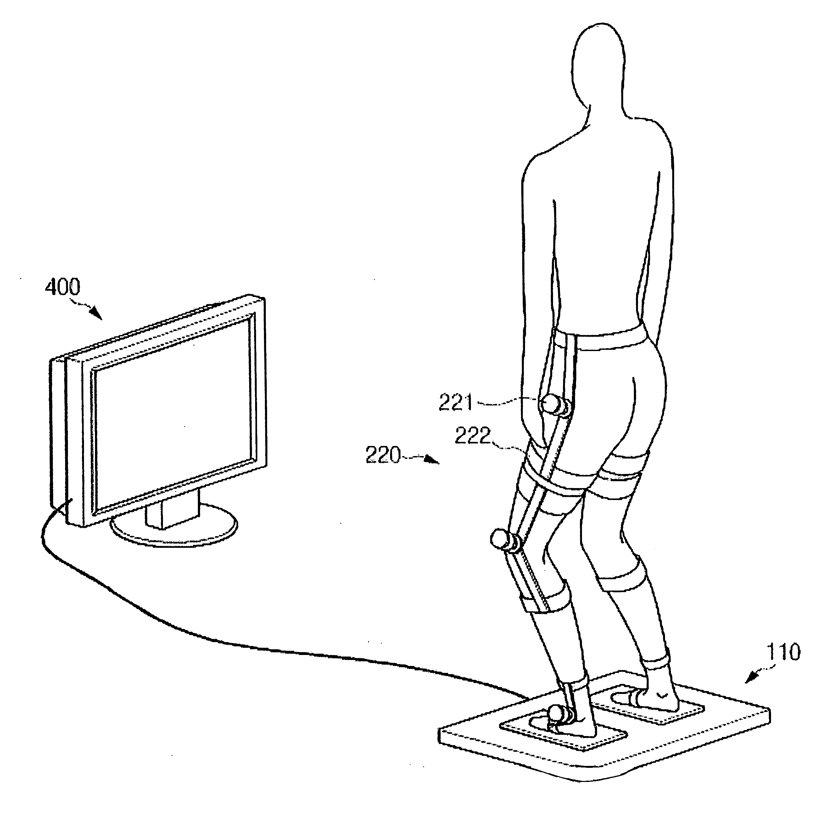
[0057] The weight-measuring part 100 is a part for measuring weight load that varies according to user motion, and disposed at a position contacting the bottom of a lower limb in order to measure the weight loaded on a lower limb. The weight-measuring part 100 may be provided to measure only one lower limb, which may be a paralyzed one. Of course, the weight-measuring part 100 can be configured to measure the weight loaded on both lower limbs.

[0058] As shown in FIG. 4a, a force plate 110 including at least one pressu...


PUM


Abstract

The present invention relates to an apparatus and method for lower-limb rehabilitation training of a patient with lower limb paralysis. The invention measures the usage of the paralyzed lower limb, and based upon the measurement, forces patients with lower limb paralysis to use partially paralyzed muscles which they are not likely to use. The apparatus can measure the weight load and the angle of the joint, and by using the measure values as variables, display the condition of paralysis to the patient so that he/she can recognize his/her present condition of paralysis, and enable the user to training through feedback. The joint includes all of knee joint, ankle joint and hip joint of the lower limb, and the movement of important muscles of the lower limb can be detected. With the apparatus attached, the patient can perform a balance training of alternatively raising the paralyzed lower limb and the normal limb, a standing training of bending and straightening both knees of the lower limbs and a walking training of using the both lower limbs.

Description

CLAIM OF PRIORITY [0001] This application makes reference to and claims all benefits accruing under 35 U.S.C. §119 from an application for “APPARATUS AND METHOD FOR LOWER-LIMB REHABILITATION TRAINING USING WEIGHT LOAD AND JOINT ANGLE AS VARIABLES” earlier filed in the Korean Intellectual Property Office on Mar. 24, 2005 and there duly assigned Serial No. 2005-24333. BACKGROUND OF THE INVENTION [0002] 1. Field of the Invention [0003] The present invention relates to an apparatus and method for lower-limb rehabilitation training of a patient with a paralyzed lower limb (hereinafter will be referred to “patient with lower-limb partial paralysis”). Particularly, the apparatus for lower-limb rehabilitation training of the invention can measure changes in the weight loaded on the lower limb and in the angle of a joint while using the changes in the weight and the joint angle as variables in order to measure the condition of paralysis of the lower limb. In addition, the apparatus of the in...

Claims


Application Information

Patent Timeline
Patent Type & Authority Applications(United States)
IPC IPC(8): A63B71/00A63B22/00
CPCA61B5/1071A61B5/1116A61B5/4519A61B5/4528A63B21/00047A63B23/04A63B26/003A63B2208/0204A63B2220/16A63B2220/51A63B2230/62A61B5/6828A61B5/6823A47G19/14A47J41/0005A47J41/022
Inventor LEE, YANG-SOO
Owner KYUNGPOOK NAT UNIV IND ACADEMIC COOP FOUND
Why Eureka
Try Eureka