Blood pressure monitor

a blood pressure monitor and automatic technology, applied in the field of automatic blood pressure monitors, can solve the problems of high cost for the average potential user, and large volume of automatic monitors,

Inactive Publication Date: 2006-09-28
QUICARE
View PDF16 Cites 12 Cited by
  • Summary
  • Abstract
  • Description
  • Claims
  • Application Information

AI Technical Summary

Benefits of technology

[0048] allowing the gas to escape from the bladder through the exit hole, gradually depressurizing the bladder to a pressure lower than the diastolic and reducing the degree of occlusion of the artery;
[0058] preventing or restricting the flow of propellant from said supply chamber into said intermediate chamber;
[0060] allowing the gas to escape from the bladder through the exit hole, gradually depressurizing the bladder to a pressure lower than the diastolic and reducing the degree of occlusion of the artery;
[0066] In the embodiments of the automatic blood pressure monitor of the invention comprising an intermediate chamber, the supply chamber can be filled before the monitor is attached to the body. The flow of propellant from the supply chamber into the intermediate chamber can be prevented by use of a valve and the flow of propellant from the supply chamber into the intermediate chamber can be restricted by use of a very small hole between the two chambers. In one embodiment, the valve between the propellant supply chamber and the intermediate chamber can be opened and the valve between the intermediate chamber and the bladder closed (and vice versa) simultaneously by a single action.
[0072] opening the seal in the blood flow occluding bladder allowing the gas to escape from the bladder through the exit hole in the bladder, gradually depressurizing the bladder and reducing the degree of occlusion of the artery;

Problems solved by technology

All of these elements, especially the pump, the electric valve, and the significant power requirements of the pump combine to make the majority of automatic monitors expensive for the average potential user, the relative expense being all the more pronounced for a device that is normally not used frequently.
Additionally, inclusion of all of the above elements results in relatively bulky devices and limits the ability of manufacturers to reduce the size of monitors to pocket-size dimensions which can be conveniently carried out of the house on business trips, vacations, etc.

Method used


Image

  • Blood pressure monitor
  • Blood pressure monitor
  • Blood pressure monitor

Examples


Embodiment Construction

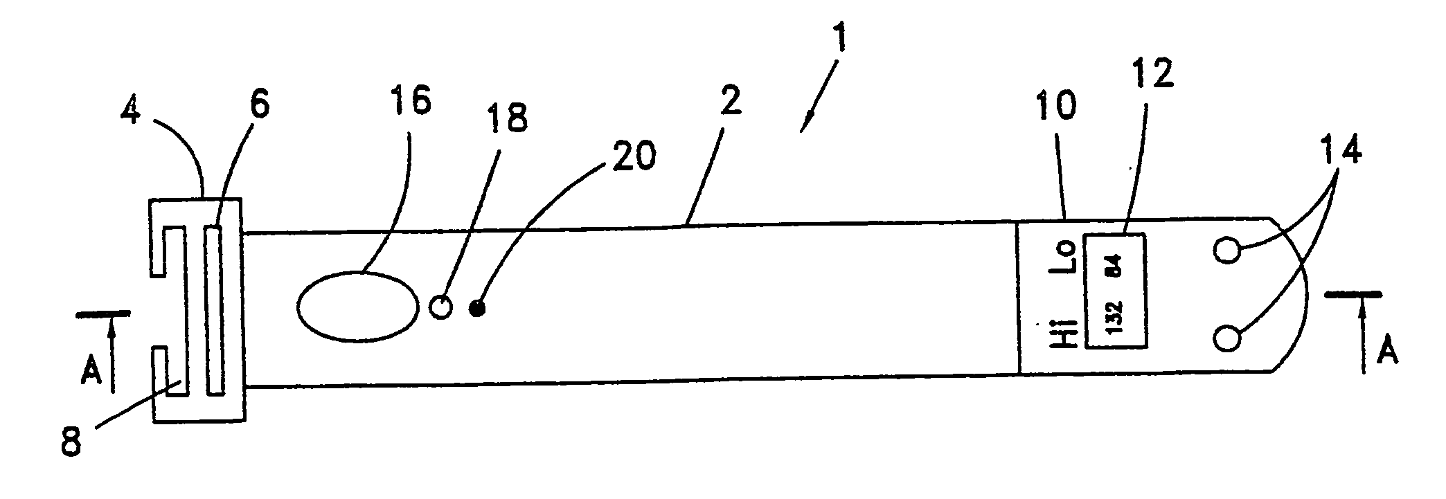
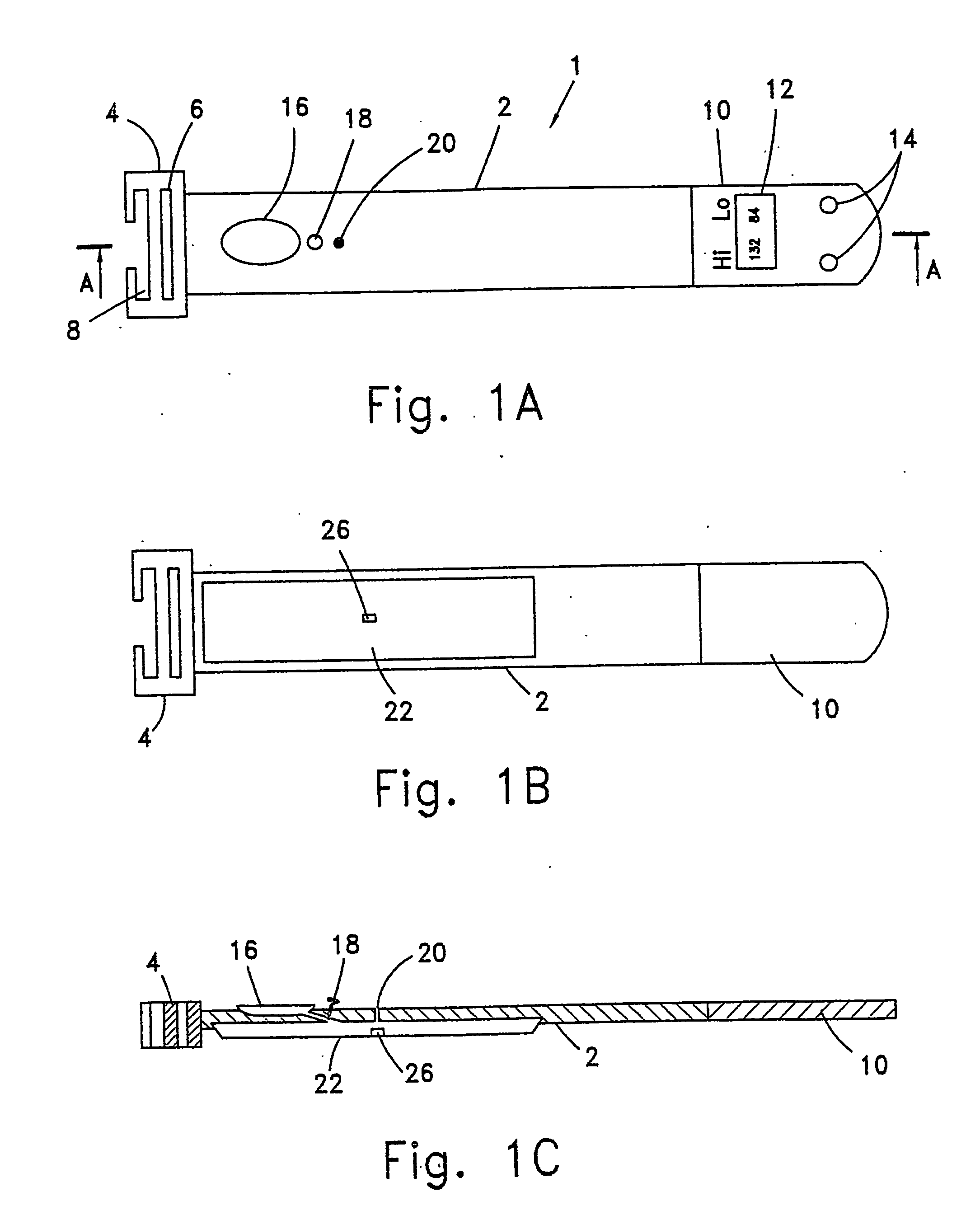
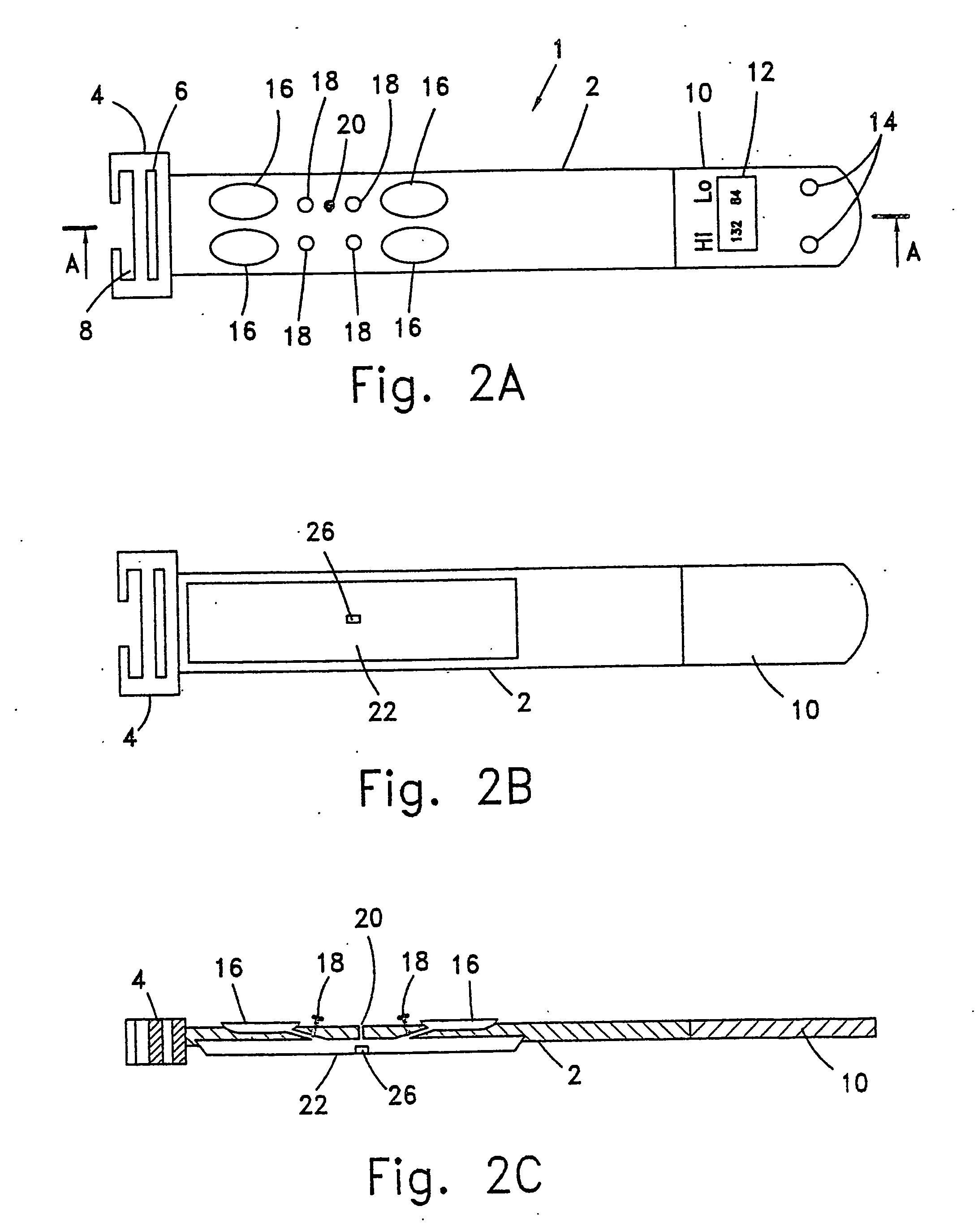
[0089] In conventional automatic devices for measuring blood pressure, the cuff, which surrounds the limb at the location where the blood is measured, contains an inflatable bladder. The bladder is initially inflated by using the electro-pneumatic unit to pump in air until a high enough pressure is obtained to occlude the flow of blood through the artery. The air is then slowly released from the cuff and the pressure decreases through values of the systolic pressure and the diastolic pressure in the artery.

[0090] The present invention accomplishes its goals by eliminating several of the more expensive and sizeable elements found in automatic home monitoring devices for blood pressure measurement that are listed hereinabove. Specifically the device of the invention does not have an electro-pneumatic unit to inflate and deflate the cuff. The device of the invention uses a pressure generator comprised of a propellant supply chamber, which is prefilled with a quantity of suitable prope...


PUM


Abstract

The present invention provides an automatic blood pressure monitor for measuring the arterial blood pressure at a location on a patient. The automatic monitor of the invention does not require an external pump of any type. The invention uses a propellant supply chamber containing a predetermined quantity of propellant in order to inflate a pressure occluding bladder, thus allowing the measurement to be made. All of the elements comprising the monitor are attached to or are an integral part of a strap, which supports the monitor at the desired location on the patient. The monitor of the invention is inexpensive and simple to operate and can be used by non-professional persons in non-clinical or non-laboratory environments.

Description

FIELD OF THE INVENTION [0001] The present invention is related to the field of equipment for medical testing and diagnosis. Specifically the present invention relates to automatic blood pressure monitors for making measurements at the arm, wrist and finger. More specifically the present invention relates to automatic blood pressure monitors, which are self contained, do not use an external pump, and can be used by non-professional persons in non-clinical or non-laboratory environments. BACKGROUND OF THE INVENTION [0002] Automatic home monitoring devices for blood pressure measurements at the arm, wrist, or finger have become available in ever increasing numbers of designs in recent years. [0003] Home monitors are recommended for use by persons who wish to take either periodic or sporadic measurements in order to keep track of the general state of their health especially persons in various groups that are considered potential candidates for developing high blood pressure such as over...

Claims


Application Information

Patent Timeline
Patent Type & Authority Applications(United States)
IPC IPC(8): A61B5/02A61B5/021A61B5/022
CPCA61B5/021A61B5/02241A61B5/022
Inventor WACHTENBERG, EYAL
Owner QUICARE
Why Eureka
Try Eureka