Vehicle control system and vehicle control method

a technology of vehicle control system and control method, which is applied in the direction of underwater vessels, braking components, non-deflectable wheel steering, etc., can solve the problems of fuel economy or efficiency undesirable degradation, reduced vehicle speed, and increased vehicle speed, so as to reduce unnecessary braking operations and reduce the frequency of brake system operations

Inactive Publication Date: 2006-09-28
TOYOTA JIDOSHA KK +3
View PDF6 Cites 19 Cited by
  • Summary
  • Abstract
  • Description
  • Claims
  • Application Information

AI Technical Summary

Benefits of technology

[0012] In the embodiment as described above, only the steering angle of each wheel is controlled based on the steering controlled variable in the normal region in which the unused grip range is large (i.e., the μ utilization ratio is small), and therefore the frequency of the operations of the brake system can be reduced. Also, at least one of the braking force and driving force of each wheel and the steering angle of each wheel are controlled based on the integrated controlled variable in the limit region in which the unused grip range is small (i.e., the μ utilization ratio is large), and at least one of the braking force and driving force of each wheel and the steering angle of each wheel are controlled based on the coordinated controlled variable obtained by linearly interpolating the integrated controlled variable and the steering controlled variable in the region between the normal region and the limit region. Thus, the grip force of a tire of each wheel can be optimally controlled by way of integrated control under which the steering angle and the braking / driving force are continuously and optimally combined based on the unused grip range (or μ utilization ratio).
[0013] As explained above, according to the invention, only the steering angles of the front and rear wheels are controlled so as to achieve the target vehicle body force and yaw moment in the region in which the unused grip range is large (i.e., the μ utilization range is small), so that unnecessary braking operations can be reduced. Furthermore, the coordinated control of the steering control and the braking / driving control can be efficiently performed in regions (including the limit region in which the unused grip range is small, i.e., the μ utilization range is large) other than the normal region.

Problems solved by technology

The operation of the brake actuator causes the speed of the vehicle to be reduced, and the reduction in the vehicle speed may make the driver uncomfortable in the normal region.
If the driving actuator is operated so as to compensate for the reduction of the vehicle speed, the fuel economy or efficiency may undesirably deteriorate.

Method used


Image

  • Vehicle control system and vehicle control method
  • Vehicle control system and vehicle control method
  • Vehicle control system and vehicle control method

Examples


Embodiment Construction

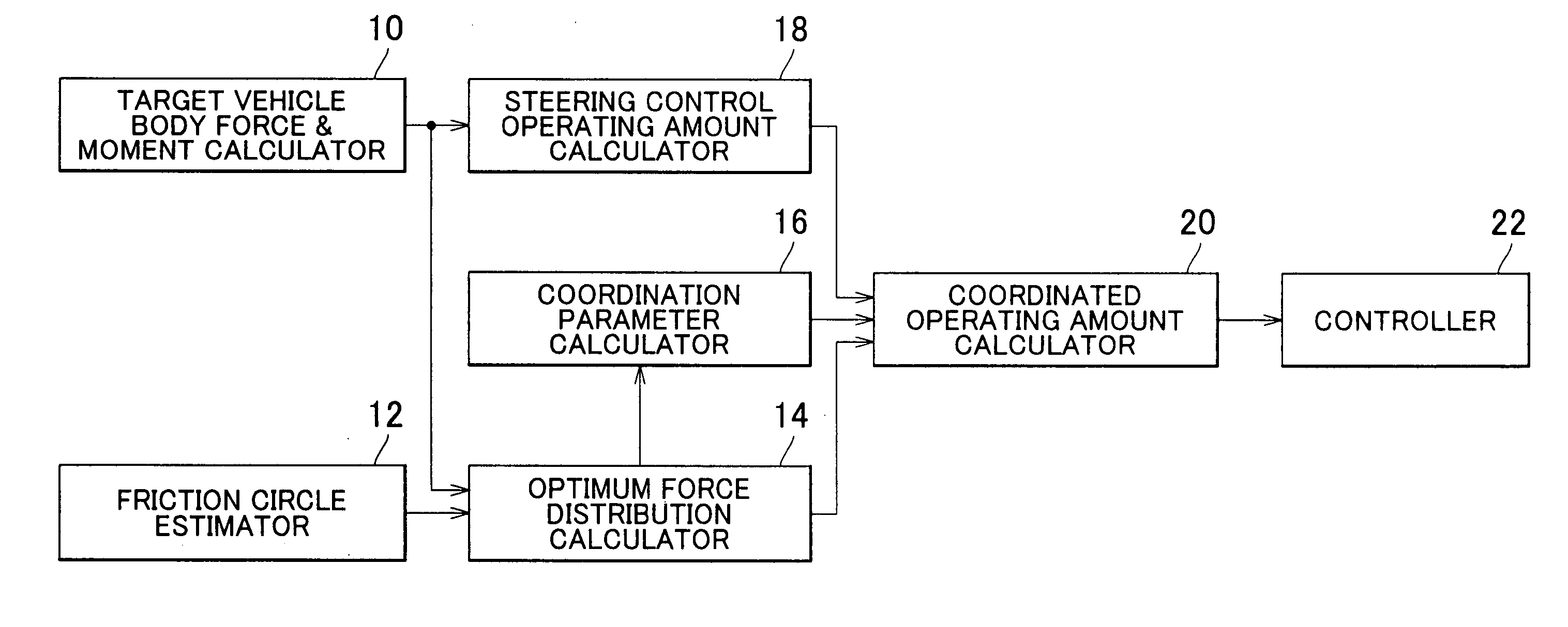
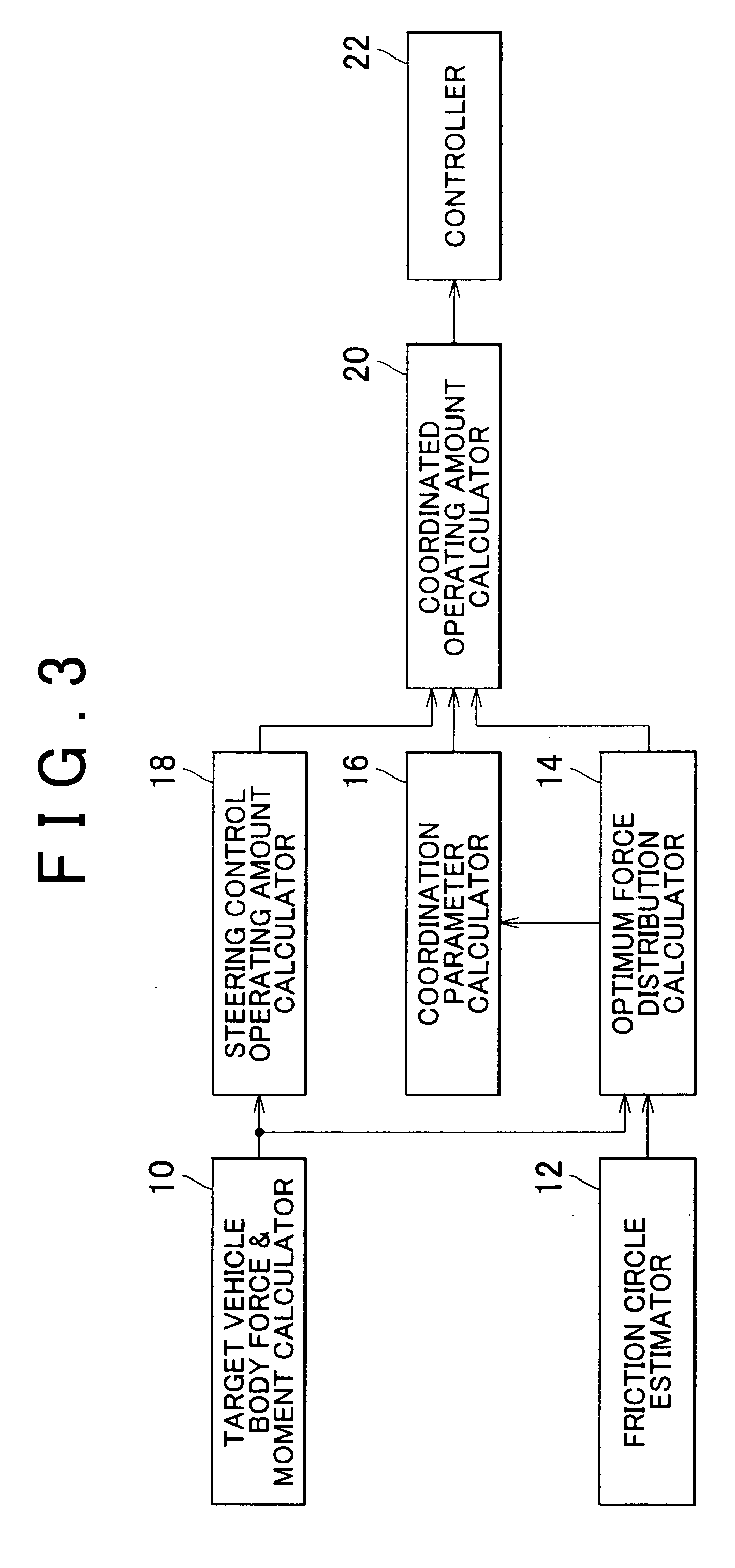
[0020] An exemplary embodiment of the invention will be described in detail with reference to the accompanying drawings. Initially, the principle of the invention will be explained. More specifically, a control logic employed in a normal region in which an unused grip range (which will be described later) is large, a control logic employed in a limit region in which the unused grip range is small, and a control logic employed in a region between the normal region and the limit region will be explained.

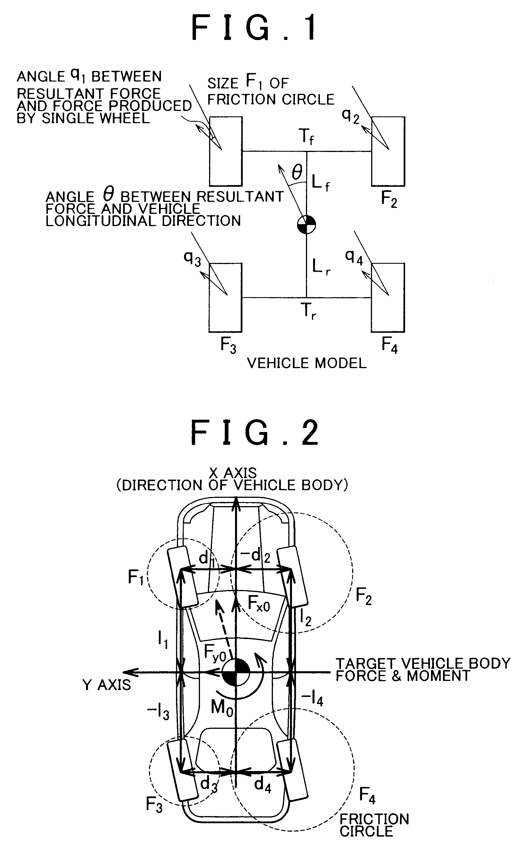
[0021] The “μ utilization ratio” as mentioned above indicates the degree of utilization of the friction between a tire and the road surface with respect to the maximum frictional force that can be generated between the tire and the road surface, namely, indicates how much of the maximum frictional force is utilized. The “μ utilization ratio” is represented by the ratio of the force generated by a wheel (or tire) to the friction circle (which will be described later) of the wheel. Mean...


PUM


Abstract

A vehicle control system includes a calculator that calculates an integrated controlled variable including a first controlled variable used for controlling the braking/driving force of each wheel so as to optimize the μ utilization ratio of the wheel and a second controlled variable used for controlling the steering angle of each wheel, based on constraints including a target resultant force to be applied to the vehicle body and a limit friction circle of each wheel, a calculator that calculates a steering controlled variable used for controlling only the steering angle of each wheel so as to achieve the target resultant force, and a controller that controls only the steering angle of each wheel, or the steering angle and braking/driving force of each wheel, based on a controlled variable obtained by linearly interpolating the integrated controlled variable and the steering controlled variable.

Description

INCORPORATION BY REFERENCE [0001] The disclosure of Japanese Patent Application No. 2005-87350 filed on Mar. 24, 2005, including the specification, drawings and abstract, is incorporated herein by reference in its entirety. BACKGROUND OF THE INVENTION [0002] 1. Field of the Invention [0003] The invention generally relates to a vehicle control system and a vehicle control method, and more particularly to a vehicle control system and a vehicle control method which provide desired vehicle body force and yaw moment by controlling only the steering angles of the front and rear wheels in a normal region in which an unused grip range is large, thereby to suppress unnecessary braking, and which is able to efficiently perform coordinated control of braking / driving control and steering control in regions, including a limit region in which the unused grip range is small, other than the normal region. [0004] 2. Description of Related Art [0005] As a conventional technique for controlling the st...

Claims


Application Information

Patent Timeline
Patent Type & Authority Applications(United States)
IPC IPC(8): G06F19/00B60T8/1755B60W10/00B60W10/04B60W10/06B60W10/18B60W10/184B60W10/20B60W30/00B60W30/02B60W30/045B62D6/00B62D101/00B62D137/00F02D29/02
CPCB60T8/1755B60T2260/022B60T2260/08B60W10/04B60W10/18B60W10/20B60W30/045B60W40/101B60W2520/26B62D6/003B62D6/006B62D7/159
Inventor ONO, EIICHIHATTORI, YOSHIKAZUMURAGISHI, YUJI
Owner TOYOTA JIDOSHA KK
Why Eureka
Try Eureka