
Client terminal device and client server system

a client server and terminal technology, applied in the field of client terminal devices and client server systems, can solve the problems of user misguided thinking that there are no operation signals, user will misguided think, and unnecessarily depress the input buttons of the remote continuously

Inactive Publication Date: 2006-09-28
FUNAI ELECTRIC CO LTD
View PDF6 Cites 16 Cited by
  • Summary
  • Abstract
  • Description
  • Claims
  • Application Information

AI Technical Summary

Benefits of technology

[0009] It is an object of the present invention to provide a client terminal device and a client server system that can receive operation signals at more suitable timing.
[0017] Moreover, during the inhibition of the reception of the operation signals by the reception regulation section, the inhibition can be informed by the information section. Consequently, the problem that the user thinks that the operation signals might not be transmitted to the client terminal device and feel uneasy can be solved.
[0019] According to the third aspect of the present invention, it is a matter of course that the similar advantages to those of the second aspect can be achieved. Besides, the reception regulation section calculates the time required until all of the output information have been outputted to the output section, based on the amount of the output information stored in the storage section at the point of time when the signal reception signal received the one operation signal from the remote controller. Therefore the reception regulation section can inhibit the reception of the operation signals transmitted from the remote controller by the signal reception section until the calculated time has elapsed. Consequently, the operation signals received by the signal reception section after the one operation signal are valid operation signals that had been transmitted after the ascertainment of the completion of the output of the output information corresponding to the operation signals received by the signal reception section prior to the one operation signal. Consequently, the client terminal device can receive the operation signals at more suitable timing.
[0020] According to the fourth aspect of the present invention, it is a matter of course that the similar advantages to those of the second aspect can be achieved. Besides, the reception regulation section can put a mark to the output information that is lastly outputted to the output section in the output information stored in the storage section at the point of time when the signal reception section receives the one operation signal from the remote controller. Therefore the reception regulation section can inhibit the reception of the operation signals transmitted from the remote controller by the signal reception section until the output information with the mark is outputted to the output section. Consequently, the operation signals received by the signal reception section after the one operation signal are valid operation signals that has been transmitted after the ascertainment of the completion of the output of the output information corresponding to the operation signals received by the signal reception section prior to the one operation signal. Consequently, the client terminal device can receive the operation signals at more suitable timing.
[0021] According to the fifth aspect of the present invention, it is a matter of course that the similar advantages to those of the second aspect can be achieved. Besides, the reception regulation section can obtain the residual quantity of the output information stored in the storage section at the point of time when the signal reception section receives the one operation signal from the remote controller. Therefore the reception regulation section can inhibit the reception of the operation signals transmitted from the remote controller by the signal reception section until the amount of the output information outputted to the output section from the point of time when the residual quantity has been obtained. Consequently, the operation signals received by the signal reception section after the one operation signal are valid operation signals that had been transmitted after the ascertainment of the completion of the output of the output information corresponding to the operation signals received by the signal reception section prior to the one operation signal. Consequently, the client terminal device can receive the operation signals at more suitable timing.
[0022] According to the sixth aspect of the present invention, it is a matter of course that the similar advantages to those of any one of the second to the fifth aspects can be achieved. Besides, the inhibition of the reception of the operation signals by the reception regulation section can be informed with the information section during the inhibition. Consequently, the problem in which a user thinks that no operation signals might be transmitted to the client terminal device and feel uneasy can be solved.

Problems solved by technology

In this case, the user will misguidedly think that no operation signals have been transmitted to the client terminal device, and will unnecessarily depress the input buttons of the remote continuously, for example.
As a result, the client terminal device has the problems such that the operation of the client terminal device stops, or that the client terminal device performs its operations excessively to cause a result that the user does not desire.
In addition, the client terminal device also has the problem that the user will misguidedly think that no operation signals have been transmitted to the client terminal device and feel uneasy.
However, the method disclosed in Patent Document 1 causes the following problem in some particular lengths of the certain periods.
Moreover, the problem in which a user misguidedly think that no operation signals have been transmitted to the client terminal device and feel uneasy cannot be solved.

Method used


Image

  • Client terminal device and client server system
  • Client terminal device and client server system
  • Client terminal device and client server system

Examples


Embodiment Construction

[0030] In the following, the best mode for implementing the present invention is described in detail by reference to the attached drawings. Here, the scope of the invention is not limited to the shown examples.

[0031] The configurations of a client server system, a server device and a client terminal device are described.

[Configuration of Client Server System]

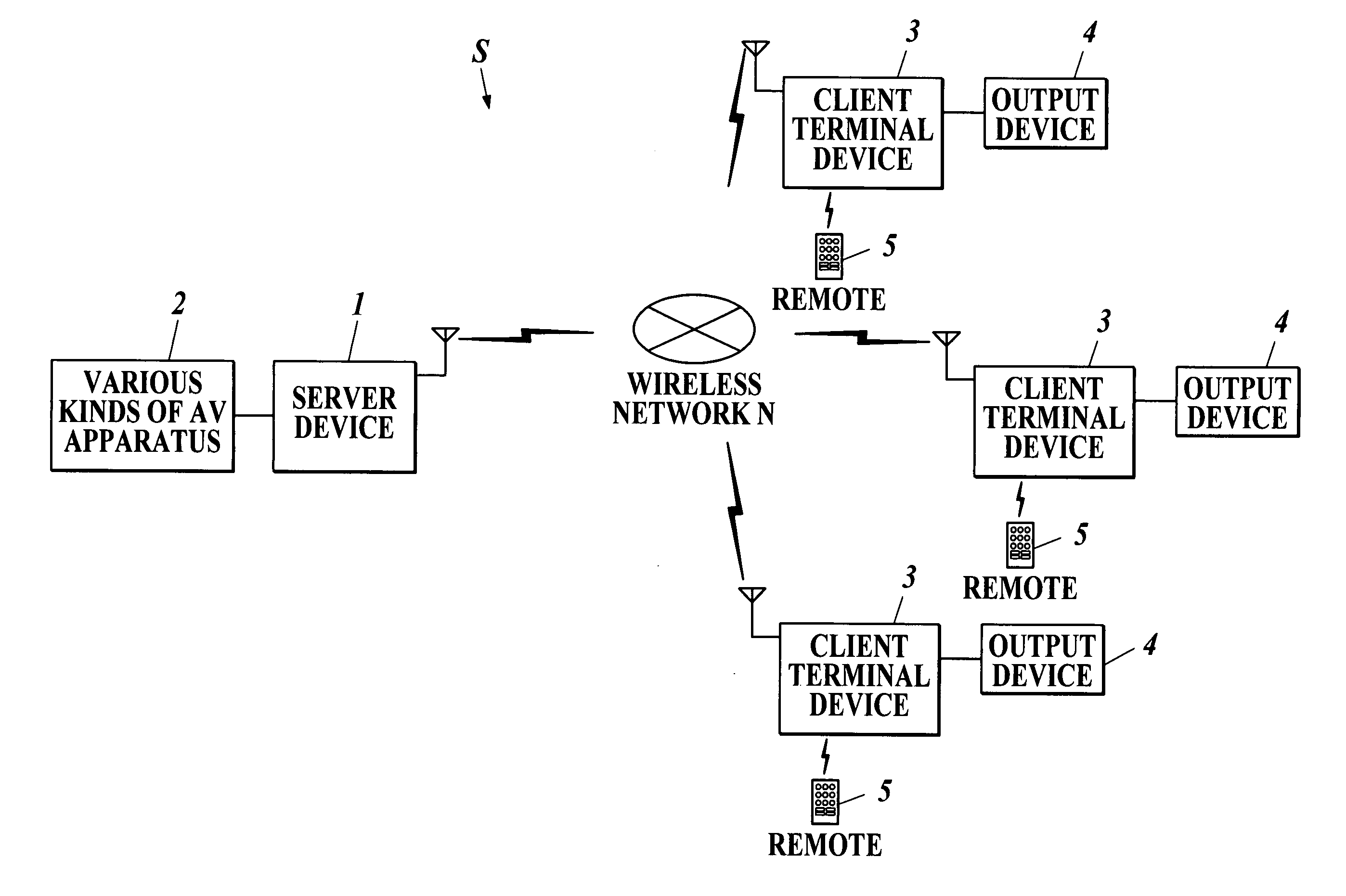
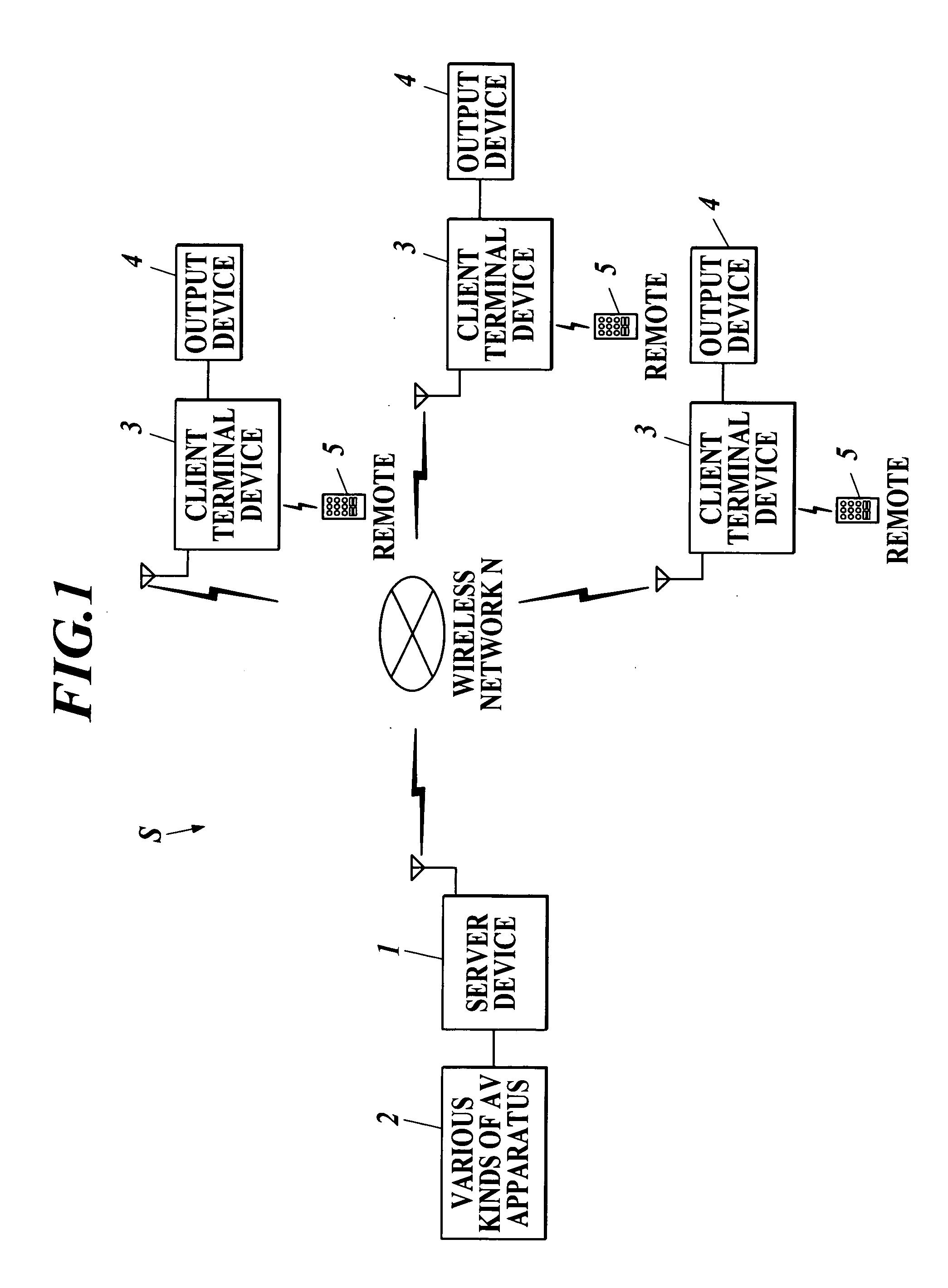
[0032] For example, as shown in FIG. 1, a client server system S comprises a server device 1 connected with various kinds of AV apparatus 2, a plurality of client terminal device 3, each of which is connected with an output device 4 as output section and is capable of being operated by a remote controller 5 (hereinafter referred to as a remote 5), and the like. The server device 1 and the client terminal device 3 are connected with each other through a wireless network N, and the client server system S is configured to enable the server device 1 and the client terminal device 3 to send and receive information mutually.

[0033]...


PUM


Abstract

A client terminal device and a client server system that can receive operation signals at more suitable timing are provided. In the client server system equipped with a client terminal device and a server device that is connected with the client terminal device through a wireless network, the client terminal device is provided with a buffer that stores content information corresponding to the operation signals from a remote controller sent by the server device, a reception regulation program making CPU inhibit reception of the operation signals sent from the remote controller by the signal reception unit until completion of outputting of the content information temporarily stored in the buffer to an output device after one operation signal has been received from the remote controller, and an informing unit informing inhibition of reception of the operation signals during inhibition.

Description

BACKGROUND OF THE INVENTION [0001] 1. Field of the Invention [0002] The present invention relates to a client terminal device and a client server system. [0003] 2. Description of the Related Art [0004] In recent years, a system for providing a client terminal device with information (content information) from a server device through a network has been used. A plurality of kinds of audio visual (AV) apparatuses such as a television device, a video recorder, a personal video recorder (PVR), a tuner for the broadcasting satellite (BS) broadcast or the communication satellite (CS) broadcast, a set top box (STB), a digital versatile disk (DVD) player, an audio device and the like is connected to the server device. The system is configured to be able to transfer the content information corresponding to the AV equipment connected to the server device from the server device to the client terminal device. [0005] Here, a user of the client terminal device operates the client terminal device, ...

Claims


Application Information

Patent Timeline
Patent Type & Authority Applications(United States)
IPC IPC(8): G06F15/16G06F13/00H04N5/44H04N7/173
CPCH04N21/42204H04N21/43637H04N21/44222H04N21/647
Inventor NAKASE, TAKAFUMI
Owner FUNAI ELECTRIC CO LTD
Learn More