Internal fuel manifold with airblast nozzles

a fuel manifold and airblast technology, applied in the direction of combustion process, turbine/propulsion fuel flow conduit, lighting and heating apparatus, etc., can solve the problem of unfavorable fuel manifold interior heating

Active Publication Date: 2006-10-05
PRATT & WHITNEY CANADA CORP
View PDF55 Cites 52 Cited by
  • Summary
  • Abstract
  • Description
  • Claims
  • Application Information

AI Technical Summary

Benefits of technology

[0005] It is therefore an object of this invention to provide an improved fuel injection system.

Problems solved by technology

However, incorporating such airblast nozzles with an internal fuel manifold, such as the type described in Applicant's published U.S. application US2004 / 0040306, may result in undue heating of the interior of the fuel manifold as a result of the flow of core air though the body of the manifold defining the main fuel passage therein.

Method used


Image

  • Internal fuel manifold with airblast nozzles
  • Internal fuel manifold with airblast nozzles
  • Internal fuel manifold with airblast nozzles

Examples


Embodiment Construction

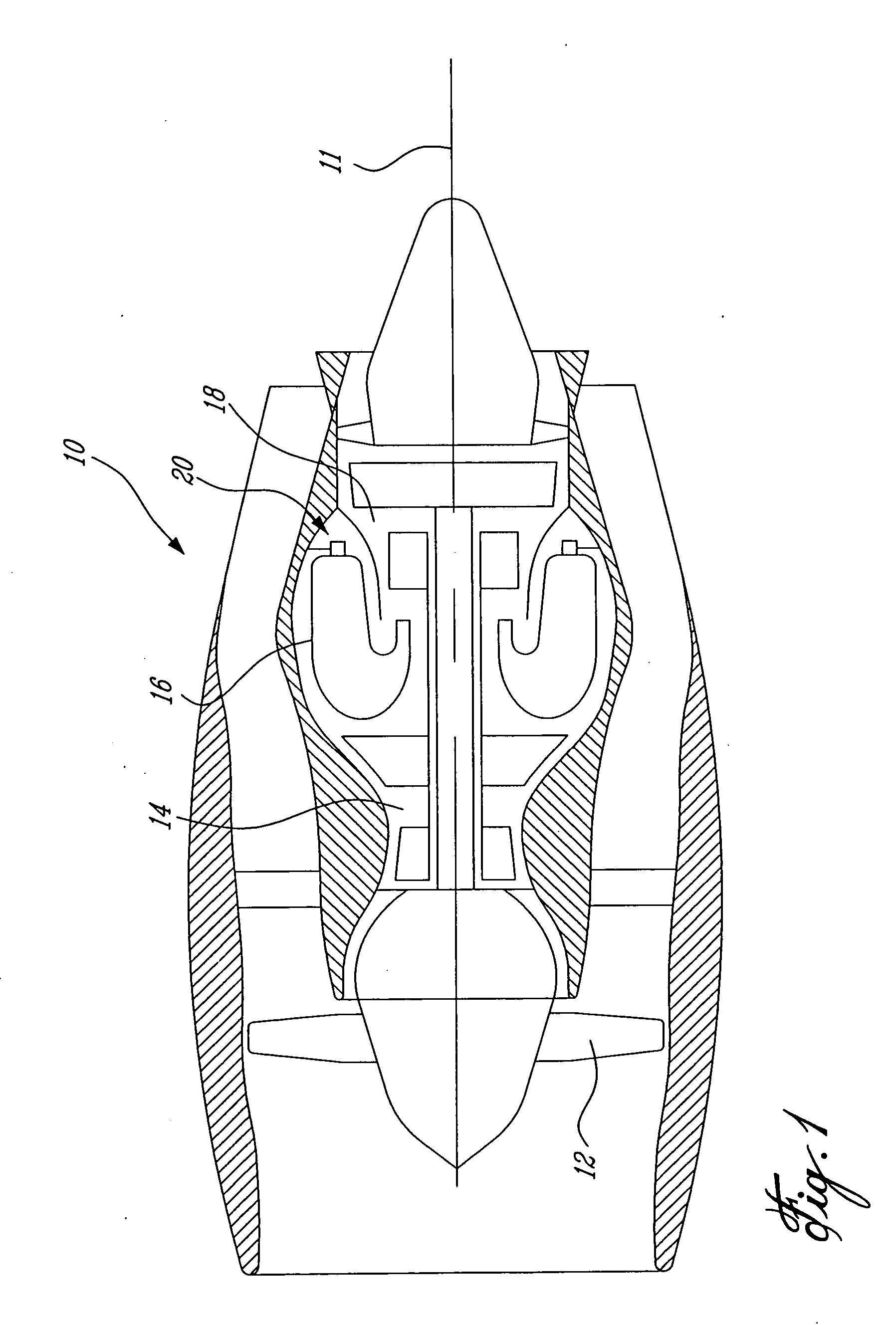
[0016]FIG. 1 illustrates a gas turbine engine 10 of a type preferably provided for use in subsonic flight, generally comprising in serial flow communication a fan 12 through which ambient air is propelled, a multistage compressor 14 for pressurizing the air, a combustor 16 in which the compressed air is mixed with fuel and ignited for generating an annular stream of hot combustion gases, and a turbine section 18 for extracting energy from the combustion gases.

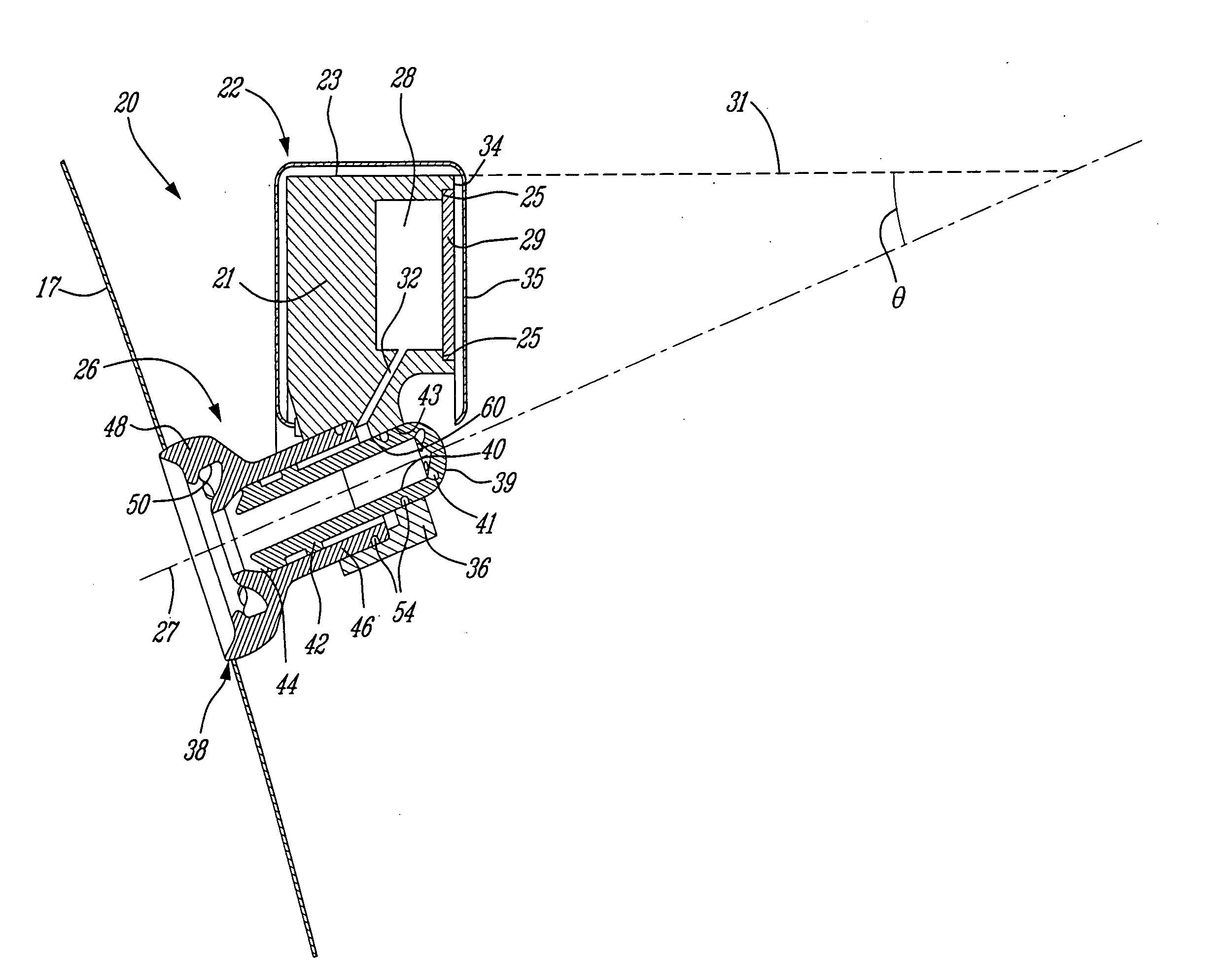
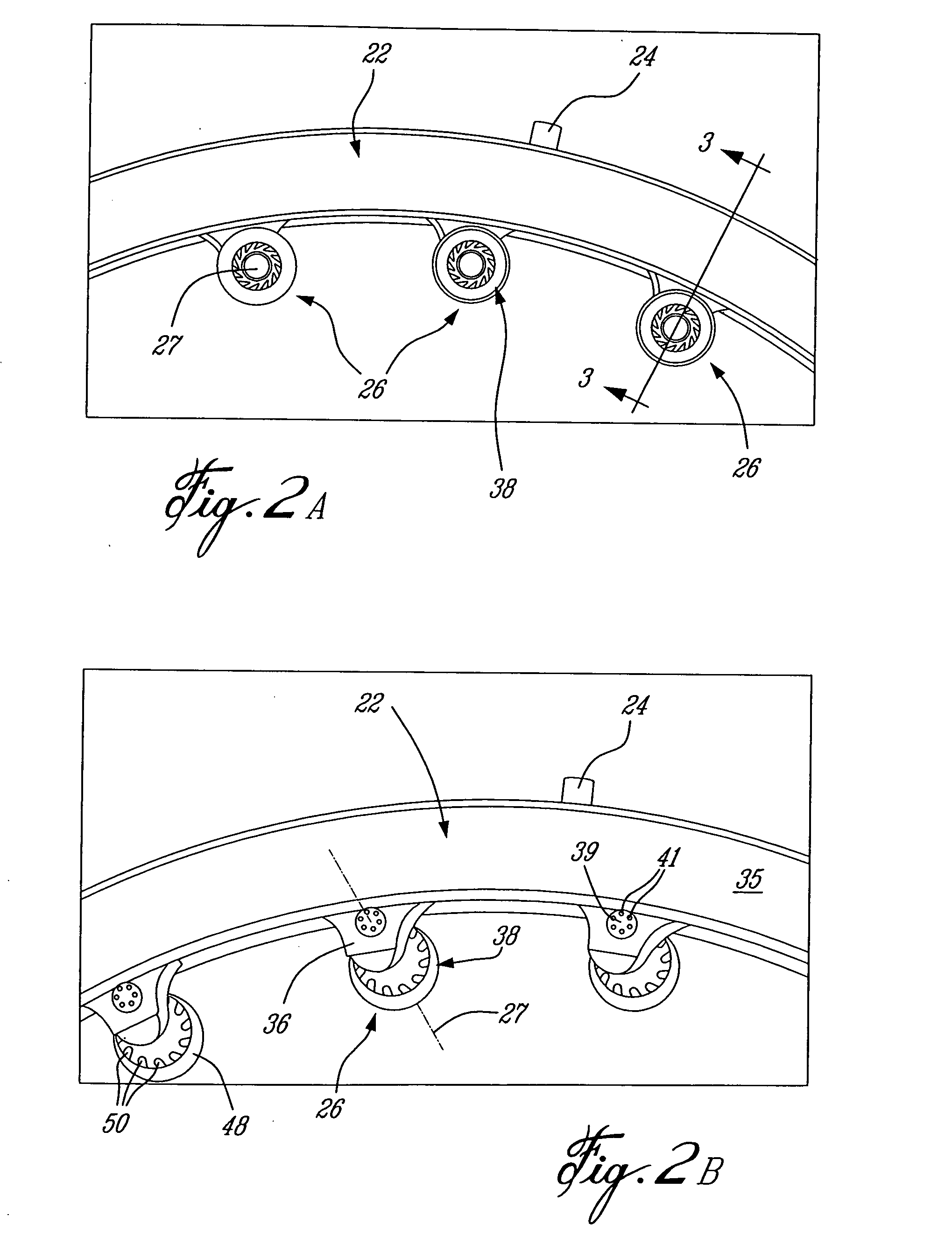
[0017] Fuel is injected into the combustor 16 of the gas turbine engine 10 by a fuel injection system 20, which includes a fuel source (not shown) and at least one fuel conveying assembly or internal fuel manifold 22, is operable to inject fuel into the combustor 16 for mixing with the compressed air from the compressor 14 and ignition of the resultant mixture. The fan 12, compressor 14, combustor 16, and turbine 18 are preferably all concentric about a common central longitudinal axis 11 of the gas turbine engine 10.

[0018] R...


PUM


Abstract

A gas turbine engine internal fuel manifold has a plurality of airblast fuel nozzles in communication with an air source such that nozzle core air does not pass through the manifold.

Description

TECHNICAL FIELD [0001] The invention relates generally to a fuel conveying members in a gas turbine engines and, more particularly, to an improved fuel injection system. BACKGROUND OF THE ART [0002] Gas turbine engine fuel injection systems generally include fuel manifolds which interconnect a plurality of fuel injecting nozzles. Typically, a plurality of fuel nozzles are circumferentially distributed about the annular fuel manifold and form a nozzle array in the combustor for injecting fuel into the combustion chamber thereof. The fuel nozzles typically comprise injector tip assemblies which constitute either a pressure atomizing nozzle or an airblast nozzle. Pressure atomizing (or air assist) nozzles inject only fuel through the core of the nozzle and use air flow about the central core to direct and atomize the fuel spray. Pure airblast nozzles provide a core airflow about which the fuel is delivered, such that energy from the core air, rather than hydraulic pressure, is used to ...

Claims


Application Information

Patent Timeline
Patent Type & Authority Applications(United States)
IPC IPC(8): F02C7/22
CPCF02C7/222F23R3/283F23K5/06F23D11/107
Inventor PROCIW, LEV ALEXANDERKOJOVIC, ALEKSANDARSHAFIQUE, HARRIS
Owner PRATT & WHITNEY CANADA CORP
Why Eureka
Try Eureka