Ejector type refrigerating cycle

a refrigerating cycle and ejector technology, applied in the direction of compression machines with several condensers, light and heating apparatus, transportation and packaging, etc., can solve the problems of reducing the performance of the cooling operation at the second vaporizing device b>62/b>, and the adjustment is not easy, so as to achieve the effect of easy adjustmen

Active Publication Date: 2006-10-05
DENSO CORP
View PDF17 Cites 51 Cited by
  • Summary
  • Abstract
  • Description
  • Claims
  • Application Information

AI Technical Summary

Benefits of technology

[0011] The present invention is made in view of the foregoing problems, and has an object to provide an ejector type refrigerating cycle havin

Problems solved by technology

It is, however, a problem in the ejector type refrigerating cycle of the above prior art that flow amounts of the refrigerant to the respective (first and second) vaporizing devices 61 and 62 are not easily adjusted, because the respective flow amounts of the refrigerant to the first and second vaporizing devices 61 and 62 must be adjusted by the one ejector 14, whereas the operation (function) of the ejector 14 for ci

Method used


Image

  • Ejector type refrigerating cycle
  • Ejector type refrigerating cycle
  • Ejector type refrigerating cycle

Examples


first embodiment

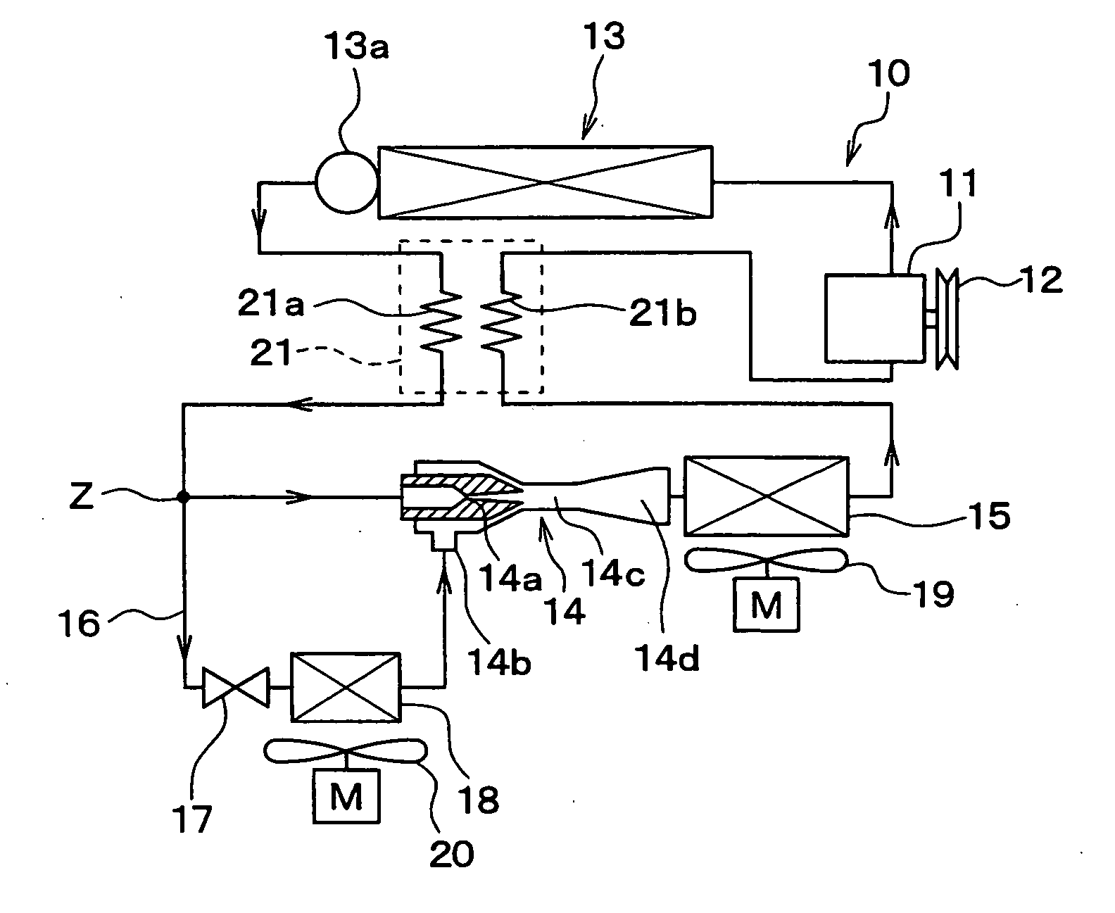
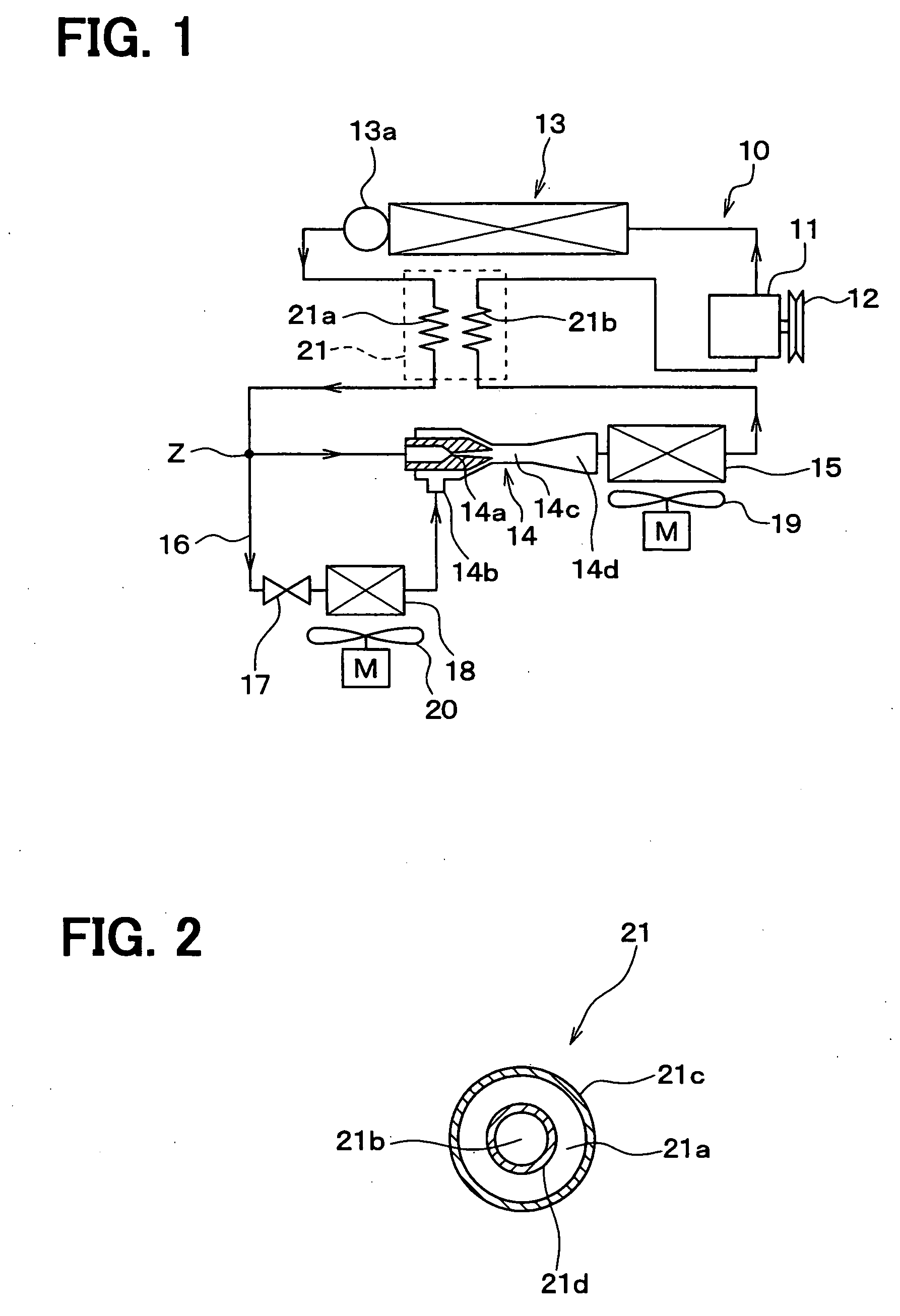
[0039]FIG. 1 shows an ejector type refrigerating cycle according to a first embodiment of the present invention, which is applied to a refrigerating cycle for an automotive vehicle. In the refrigerating cycle 10 according to this embodiment, a compressor 11 for sucking in and compressing refrigerant is driven by an engine for the automotive vehicle (not shown) via an electromagnetic clutch 12, a belt and so on.

[0040] Any type of compressor can be used as the compressor 11, for example, a capacitor variable type compressor which can adjust refrigerant discharge performance depending on variation of the discharge amount, or a fixed capacitor type compressor which can adjust refrigerant discharge performance by changing an operating rate thereof with ON-OFF of the electromagnetic clutch 12. In the case that an electrically operated compressor is used, the refrigerant discharge performance can be adjusted by controlling rotational speed of an electric motor.

[0041] A heat radiating dev...

second embodiment

FIG. 4

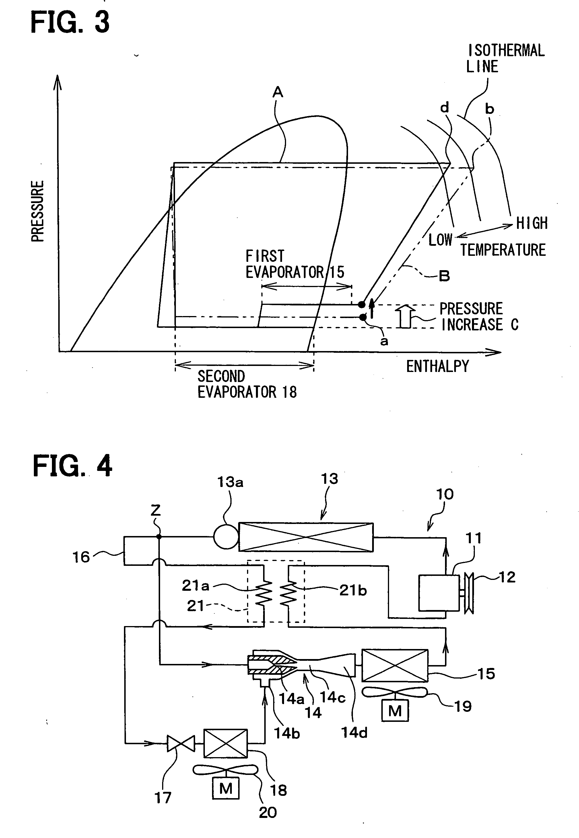
[0078] In the above first embodiment, the high-pressure side refrigerant passage 21a of the internal heat exchanger 21 is arranged at the upstream side of the bifurcating point Z for the bypass passage 16. According to a second embodiment, the high-pressure side refrigerant passage 21a of the internal heat exchanger 21 is arranged at the downstream side of the bifurcating point Z, namely at the upstream side of the restricting device 17 for the bypass passage 16.

[0079] According to the second embodiment, only the high-pressure refrigerant bifurcated to the bypass passage 16 is cooled down by the internal heat exchanger 21. The super cooling degree of the refrigerant is thereby increased, and the enthalpy of the refrigerant at the inlet side of the second vaporizing device 18 is reduced.

[0080] On the other hand, since the high-pressure refrigerant passing through the ejector 14 is not cooled down by the internal heat exchanger 21, the enthalpy of the refrigerant at the outlet...

third embodiment

FIG. 5

[0082]FIG. 5 shows a third embodiment, in which a second bypass passage 22 is added to the first embodiment. The second bypass passage 22 is bifurcated from the inlet side of the ejector 14 (the inlet side of the restricting device 17), and its downstream end is connected to the outlet side of the first vaporizing device 15.

[0083] A restricting device 23 and a third vaporizing device 24 are provided in the second bypass passage 22. The restricting device 23 is formed by a fixed restriction valve, such as a capillary tube, or an orifice, and operates as a depressurizing means for adjusting the refrigerant flow amount to the third vaporizing device 24. An electrically driven valve device can be used for the restriction device 23, so that a valve opening degree (a passage opening area) can be adjusted by an electromagnetic actuator. Air in a space, for which cooling operation is carried out, is blown to the third vaporizing device 24 by an air blowing device 25.

[0084] An outlet...


PUM


Abstract

An ejector type refrigerating cycle comprises a compressor, a heat radiating device, an ejector, and a first vaporizing device, which are connected in a circuit to form a refrigerating cycle. A bypass passage is provided between an inlet port and a suction port of the ejector, so that a part of the refrigerant is bifurcated to flow through the bypass passage. A second vaporizing device is provided in the bypass passage. An internal heat exchanger is further provided between an outlet side of the heat radiating device and the inlet side of the ejector, so that the enthalpy of the high-pressure refrigerant from the heat radiating device is reduced, to thereby increase an enthalpy difference between the inlet side and outlet side of the first and second vaporizing devices. As a result, the cooling capability by the both vaporizing devices can be improved.

Description

CROSS REFERENCE TO RELATED APPLICATION [0001] This application is based on Japanese Patent Applications Nos. 2005-105992 filed on Apr. 1, 2005, 2005-195105 filed on Jul. 4, 2005 and 2006-36532 filed on Feb. 14, 2006, the disclosures of which are incorporated herein by reference. FIELD OF THE INVENTION [0002] The present invention relates to an ejector type refrigerating cycle having an ejector for depressurizing and circulating refrigerant, multiple vaporizing devices, and an internal heat exchanger. The present invention is preferably applied to a refrigerating cycle for an air conditioning apparatus and a refrigerating apparatus. BACKGROUND OF THE INVENTION [0003] An ejector type refrigerating cycle is proposed, for example as disclosed in Japanese Patent No. 3322263, in which an ejector is used as a means for depressurizing and circulating refrigerant in the refrigerating cycle of a gas compression type. [0004] According to the above prior art (JP Pat. No. 3322263), as shown in F...

Claims


Application Information

Patent Timeline
IPC IPC(8): F25B1/06
CPCB60H1/3211B60H2001/3297F25B5/02F25B5/04F25B2500/18F25B40/00F25B41/00F25B2341/0012F25B6/04B60H2001/3298F25B9/08F25B1/00F25B43/00
Inventor SAITO, MIKATAKEUCHI, HIROTSUGUTAKANO, YOSHIAKIOSHITANI, HIROSHIISHIZAKA, NAOHISAOGATA, GOTAMAEHARA, TAKUO
Owner DENSO CORP
Why Eureka
Try Eureka