
Blade assembly for transmission of semiconductor chip

a technology of semiconductor chips and blades, applied in the direction of mechanical control devices, instruments, process and machine control, etc., can solve the problems of aluminum alloy that cannot tolerate a higher temperature, and achieve the effects of preventing detachment of blades, and facilitating rotation

Inactive Publication Date: 2006-10-05
POSANTEK
View PDF7 Cites 15 Cited by
  • Summary
  • Abstract
  • Description
  • Claims
  • Application Information

AI Technical Summary

Benefits of technology

[0008] Another objective of the present invention is to provide a blade assembly, wherein the positioning flange of the mounting ring of the pivot arm is sandwiched between the first bearing and the second bearing and the inner washer is sandwiched between the inner ring of the first bearing and the inner ring of the second bearing, thereby preventing the first bearing from pressing and jamming the second bearing due to a pressing action of the urging cap, so that the pivot arm is pivotable smoothly and stably.
[0009] A further objective of the present invention is to provide a blade assembly, wherein the top cover is formed with two positioning pins each positioned in a respective one of the two positioning holes of the blade, so that the top cover is secured on the blade rigidly and stably to prevent detachment of the blade.
[0010] A further objective of the present invention is to provide a blade assembly, wherein the blade is made of ceramic material having a relatively higher density, so that the blade has a smaller thickness and lighter weight, thereby greatly reducing the load of the pivot arm to prevent the pivot arm from being distorted or deformed due to fatigue.
[0011] A further objective of the present invention is to provide a blade assembly, wherein the pivot arm is made of a titanium alloy having a lighter weight and greater strength, so that the pivot arm has a greater support strength, thereby preventing the pivot arm from being deformed due to a larger force.

Problems solved by technology

Further, the blade 51 is made of aluminum alloy that cannot tolerate a higher temperature.

Method used


Image

  • Blade assembly for transmission of semiconductor chip
  • Blade assembly for transmission of semiconductor chip
  • Blade assembly for transmission of semiconductor chip

Examples


Embodiment Construction

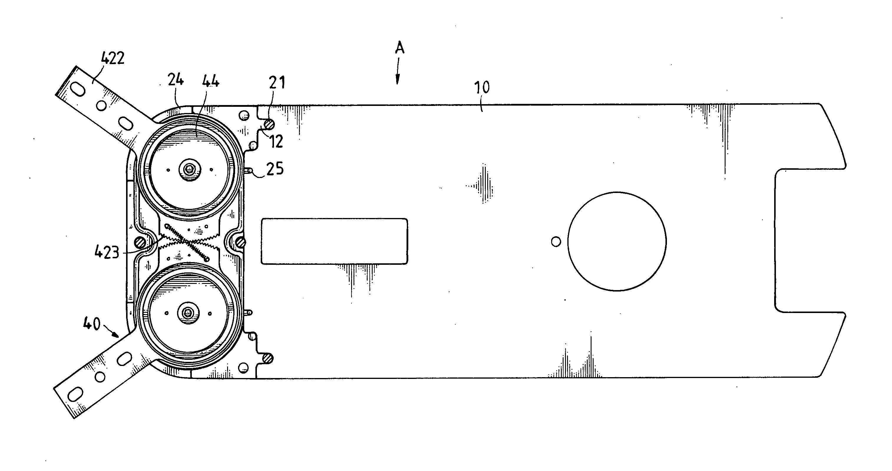
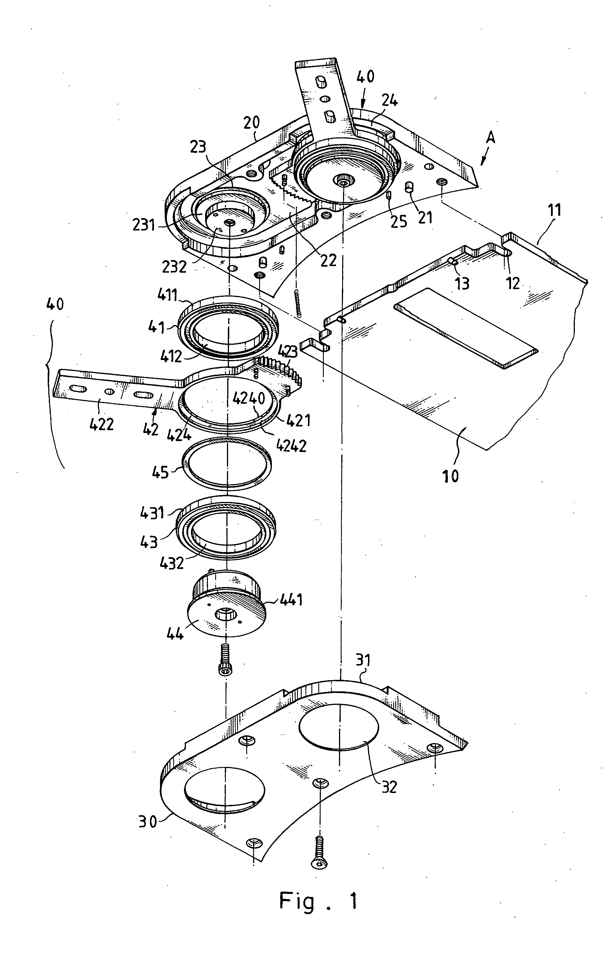
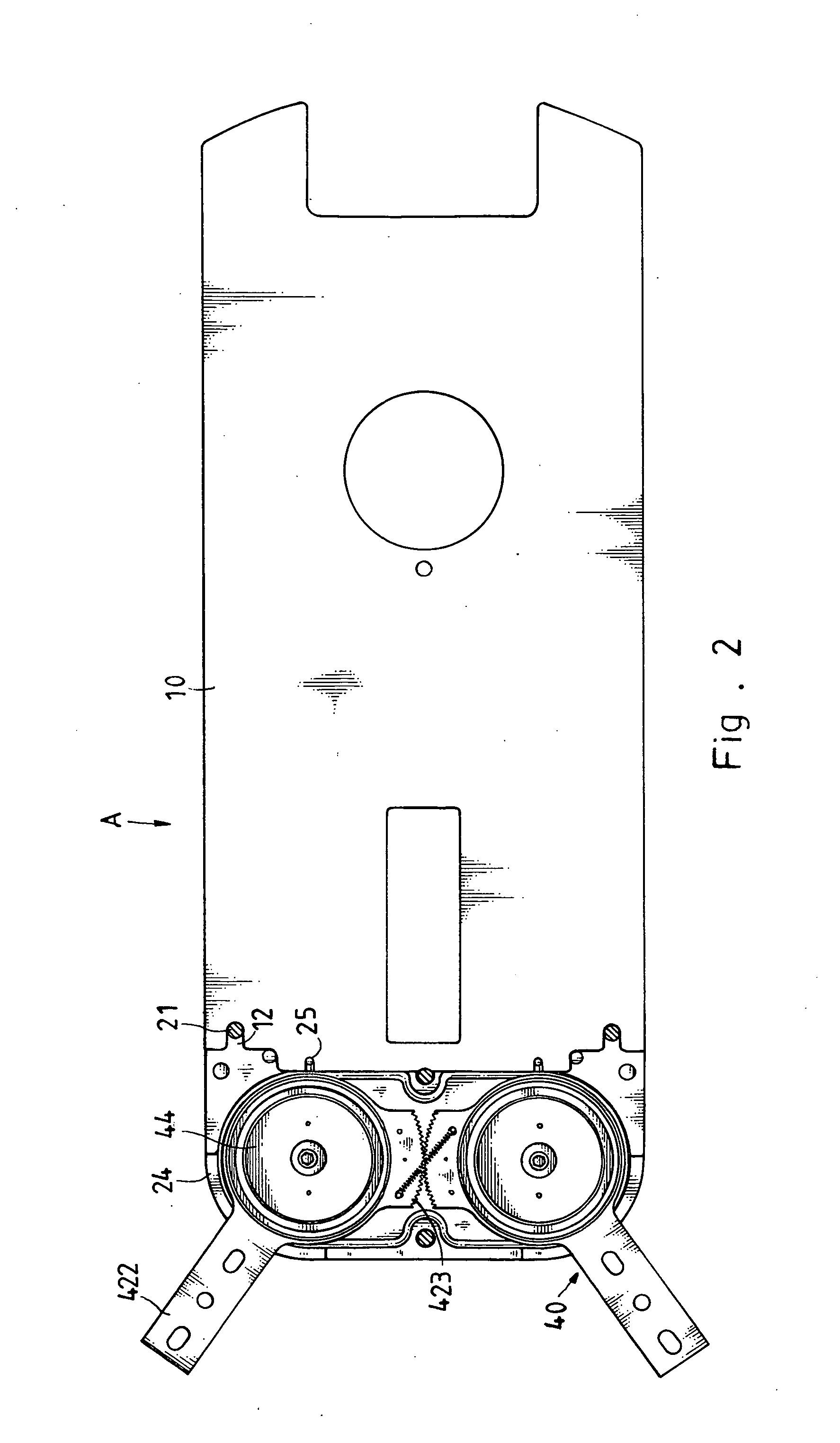
[0021] Referring to FIGS. 1-4, a blade assembly “A” in accordance with the present invention is connected to a robot arm for transmission and support of semiconductor chips. The blade assembly “A” comprises a blade 10, a top cover 20 mounted on the blade 10, a bottom cover 30 mounted on the blade 10 and combined with the top cover 20, and two pivot units 40 each pivotally mounted between the top cover 20 and the bottom cover 30.

[0022] The blade 10 has a support face 11 for supporting the semiconductor chips and has an end portion formed with two guide grooves 12.

[0023] The top cover 20 has a first end formed with two guide pins 21 each inserted into a respective one of the two guide grooves 12 of the blade 10 so that the top cover 20 is secured on the blade 10. The top cover 20 has a second end formed with a receiving recess 22 formed with two bearing seats 23 each having an annular groove 231 and a protruding locking portion 232 located in the annular groove 231.

[0024] Each of t...


PUM


Abstract

A blade assembly is connected to a robot arm for transmission of semiconductor chips and includes a blade, a top cover, a bottom cover, and two pivot units each including a pivot arm, a first bearing, and a second bearing. Thus, the positioning flange of the mounting ring of the pivot arm is sandwiched between the first bearing and the second bearing and the inner washer is sandwiched between the inner ring of the first bearing and the inner ring of the second bearing, thereby preventing the first bearing from pressing and jamming the second bearing due to a pressing action of the urging cap, so that the pivot arm is pivotable smoothly and stably.

Description

BACKGROUND OF THE INVENTION [0001] 1. Field of the Invention [0002] The present invention relates to a blade assembly, and more particularly to a blade assembly connected to a robot arm for transmission of semiconductor chips. [0003] 2. Description of the Related Art [0004] A conventional blade assembly 50 in accordance with the prior art shown in FIGS. 5-8 comprises a blade 51 having an end portion formed with two guide grooves 511, a top cover 52 mounted on the blade 51 and having a first end formed with two guide pins 521 each inserted into a respective one of the two guide grooves 511 of the blade 51 so that the top cover 52 is secured on the blade 51 and a second end formed with two bearing seats 522, a bottom cover 53 mounted on the blade 51 and combined with the top cover 52, and two pivot units 54 each pivotally mounted between the top cover 52 and the bottom cover 53 and each including a pivot arm 543 pivotally mounted between the top cover 52 and the bottom cover 53 and ha...

Claims


Application Information

Patent Timeline
Patent Type & Authority Applications(United States)
IPC IPC(8): B25J17/00
CPCH01L21/67766Y10T74/20305H01L21/68707
Inventor TU, WEN-CHANGKANG, CHU-CHING
Owner POSANTEK
Learn More