Method and machine for replacing damaged rail sections of a track

a technology for rail sections and replacement methods, applied in rail joints, constructions, ways, etc., can solve problems such as efficiency drawbacks and shortcomings of prior art methods and devices, and achieve the effect of achieving rail tension

Inactive Publication Date: 2006-10-05
FRANZ PLASSER BAHNBAUMASCHINEN IND GMBH
View PDF32 Cites 26 Cited by
  • Summary
  • Abstract
  • Description
  • Claims
  • Application Information

AI Technical Summary

Benefits of technology

[0008] It is accordingly an object of the invention to provide a method and an apparatus for replacing damaged rail segments of a track which overcome the above-mentioned disadvantages of

Problems solved by technology

The prior art methods and devices are subje

Method used


Image

  • Method and machine for replacing damaged rail sections of a track
  • Method and machine for replacing damaged rail sections of a track
  • Method and machine for replacing damaged rail sections of a track

Examples


Embodiment Construction

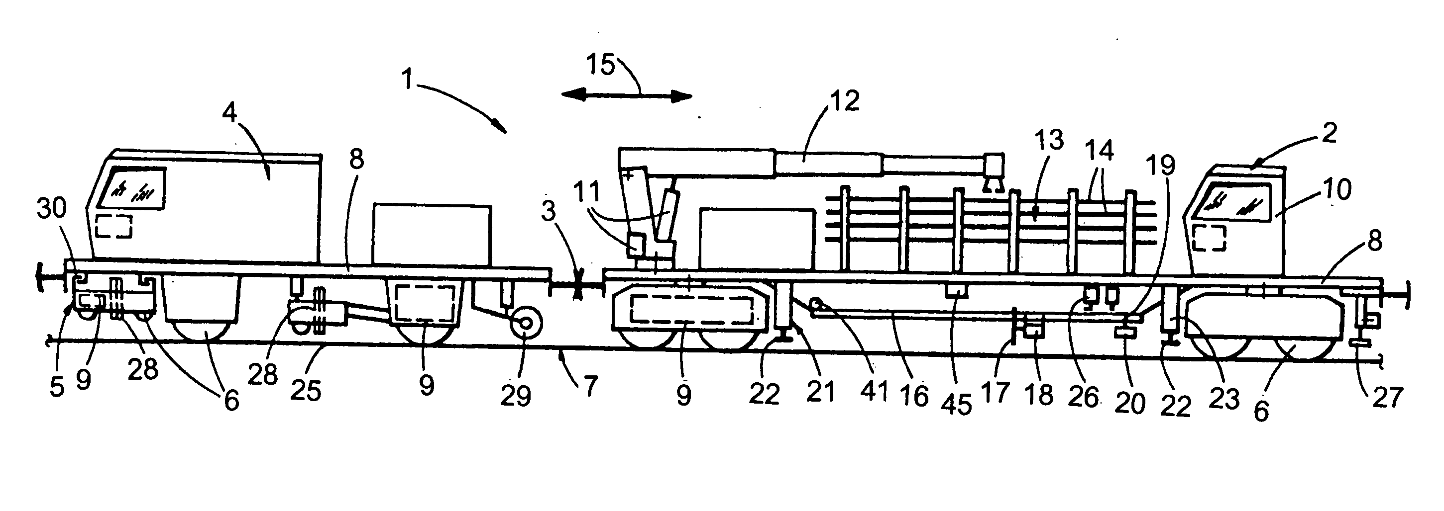
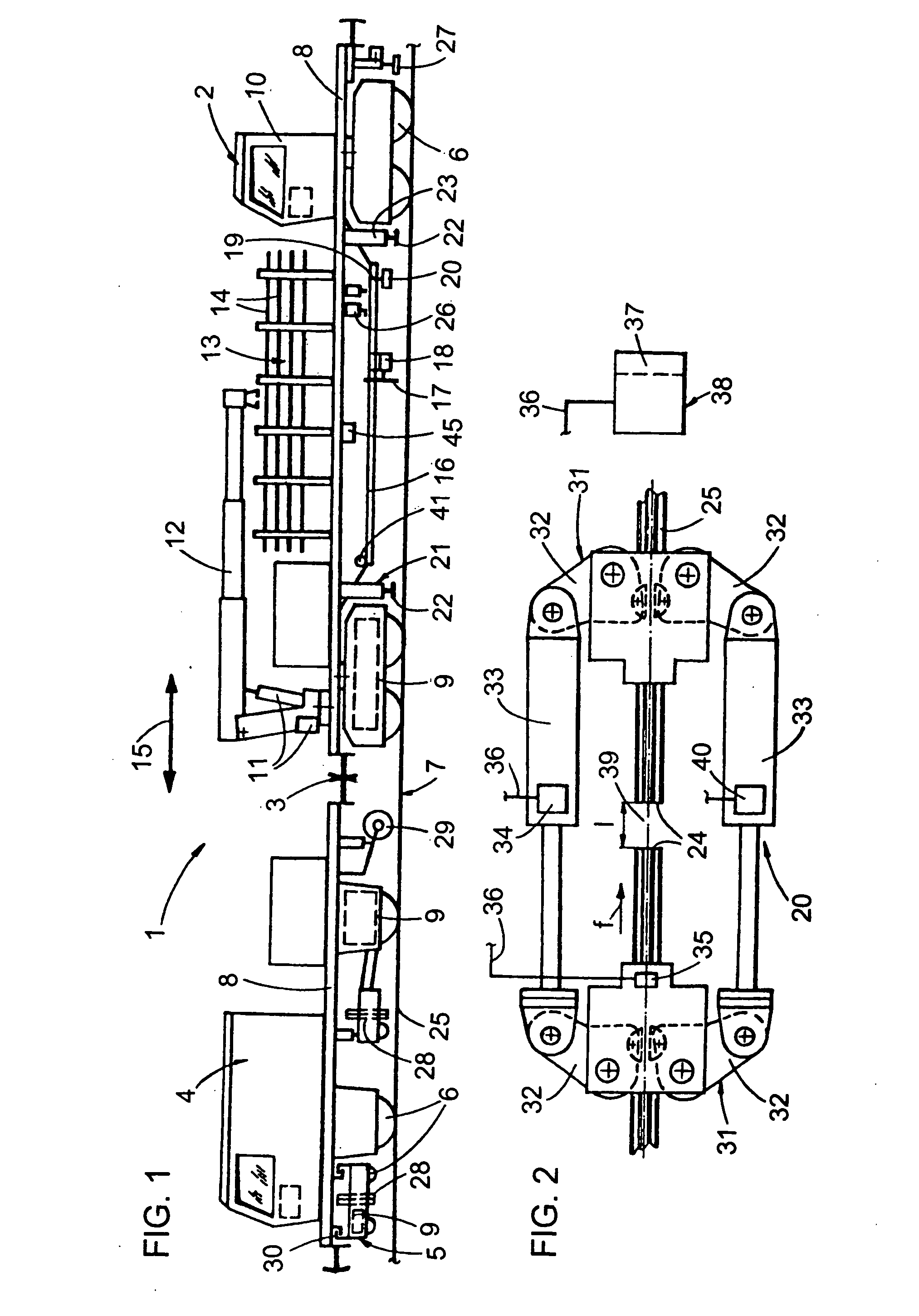
[0038] Referring now to the figures of the drawing in detail and first, particularly, to FIG. 1 thereof, there is seen a machine assembly 1 comprising a first machine 2, a second machine 4 detachably connected to the first machine by way of a coupling 3, and a third machine 5 designed to be transported by the second machine 4 during transfer travel. Each of the machines 2, 4, 5 includes a machine frame 8 that is mobile by way of on-track undercarriages 6 that run on a track 7, and each is equipped with a motive drive 9.

[0039] The first machine 2 comprises a rail storage facility 13 located between a driver's cabin 10 and a crane jib 12, the latter being vertically adjustable and rotatable by drives 11. The rail storage facility 13 is configured for transporting and storing a number of replacement rails 14 of different lengths. Provided underneath the machine frame 8, between the two ontrack undercarriages 6 placed at the ends, is a saw guide 16 extending in a longitudinal direction...


PUM


Abstract

In a method for efficiently removing a great number of damaged rail sections, after a first separating cut, the severed free rail ends are gripped by a rail pulling device connecting the rail ends to one another, and are pulled towards one another. The pulling force required for the pulling-together as well a current rail temperature are registered for calculation of that length of a replacement rail which is required for producing a desired rail tension. A second separating cut is carried out—with corresponding path measurement—spaced at a distance from the first separating cut as calculated on the basis of the selected length of the replacement rail.

Description

CROSS-REFERENCE TO RELATED APPLICATION [0001] This application claims the priority, under 35 U.S.C. § 119, of Austrian patent application A 533 / 2005, filed Mar. 30, 2005; the application further claims the benefit, under 35 U.S.C. § 119(e), of provisional patent application No. 60 / 671,014, filed Apr. 13, 2005; the prior applications are herewith incorporated by reference in their entirety.BACKGROUND OF THE INVENTION [0002] 1. Field of the Invention [0003] The invention relates to a method of removing damaged rail sections from welded rails of a track having an actual rail tension and an actual rail temperature. Following two separating cuts—wherein a rail gap and two rail ends are formed—a replacement rail is welded to the two rail ends. The invention further pertains to a machine for producing a rail weld. [0004] 2. Description of the Related Art [0005] Numerous methods or devices for welding rail ends to one another have become known in the art. By way of example, reference is had...

Claims


Application Information

Patent Timeline
IPC IPC(8): E01B29/05
CPCE01B29/02E01B31/18E01B29/44
Inventor THEURER, JOSEF
Owner FRANZ PLASSER BAHNBAUMASCHINEN IND GMBH
Why Eureka
Try Eureka