Aluminum heat exchanger

a heat exchanger and aluminum technology, applied in the direction of manufacturing tools, soldering devices, light and heating equipment, etc., can solve the problem of leakage at the joined portion of the flat tub

Inactive Publication Date: 2006-10-05
T RAD CO LTD
View PDF9 Cites 13 Cited by
  • Summary
  • Abstract
  • Description
  • Claims
  • Application Information

AI Technical Summary

Benefits of technology

[0012] Another aspect of the present invention is the aluminum-made heat exchanger according to the first aspect of the present invention, wherein the brazing metal (2) of an aluminum alloy including Si of 7.5 to 12% by weight, the core metal (1) is equivalent to A3003 of A. A. Standard (0.15% by weight of Cu, 1.2% by weight of Mn and balance ofAl: the same is applied in the following) aluminum material added with Si of 0.4 to 1.2% by weight, the sacrificial anode material (3) is equivalent to A7072 of A. A. Standard (0.1% by weight of Zn and balance is Al: the same is applied in the following) added with Mg of 0.3 to 0.75% by weight.
[0013] The aluminum-made heat exchanger according to the present invention has a structure as described above, and provides the following effects.

Problems solved by technology

That is, there may be a case such that a leakage occurs at a joined portion on the flat tube.

Method used


Image

  • Aluminum heat exchanger
  • Aluminum heat exchanger
  • Aluminum heat exchanger

Examples


Embodiment Construction

[0021] An embodiment of the present invention is described below referring to the drawings.

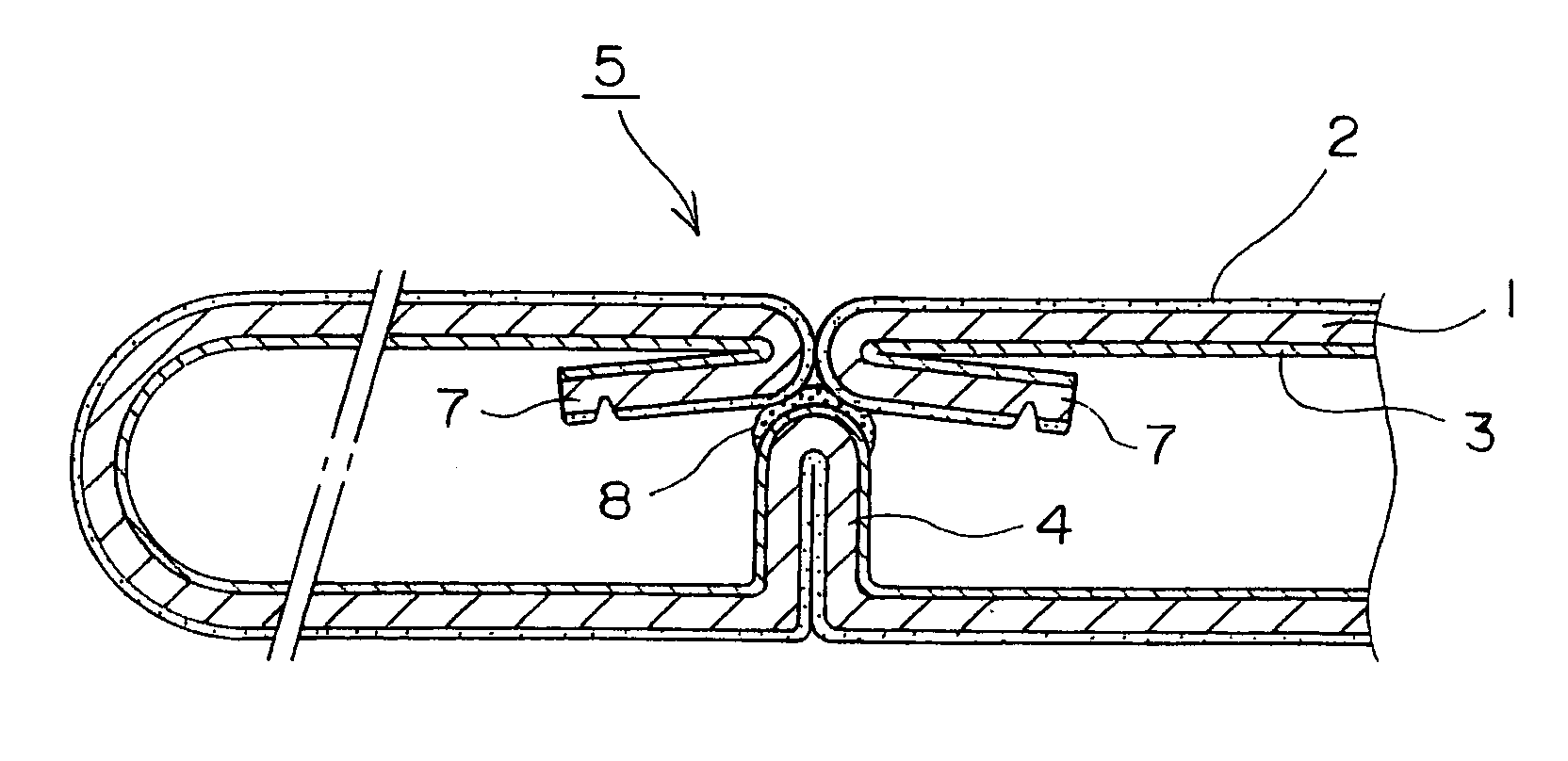
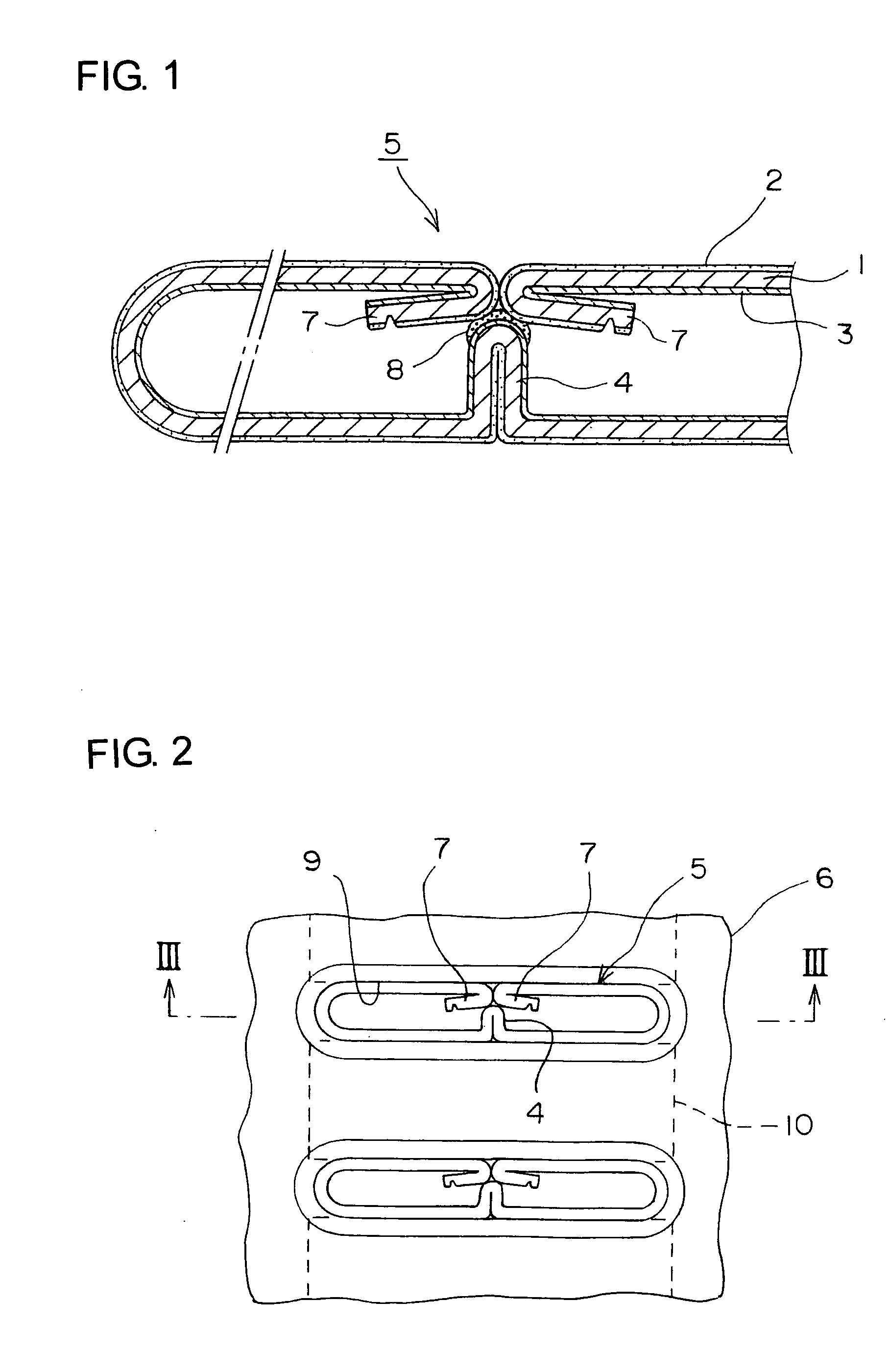
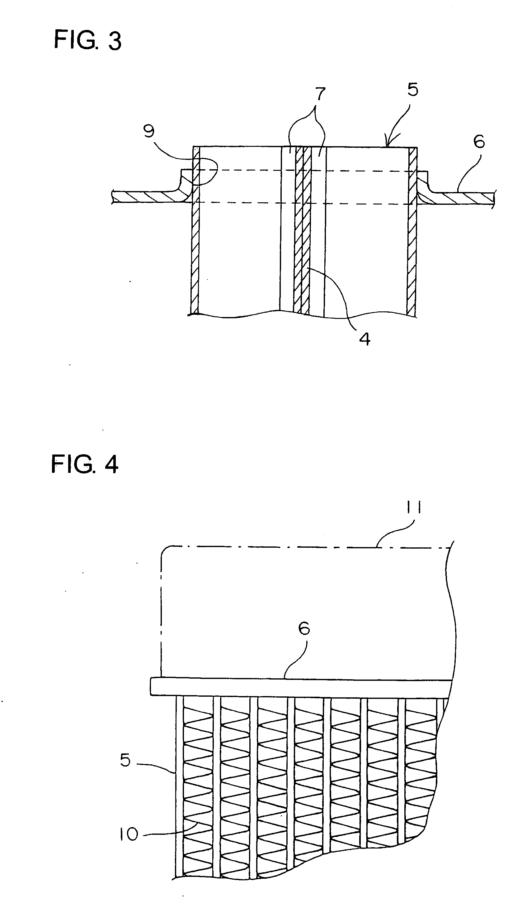
[0022]FIG. 1 shows an enlarged view of a flat tube for an heat exchanger according to the present invention, illustrating a relevant portion before brazing; FIG. 2 shows a plane view of the heat exchanger, illustrating the assembly state thereof; FIG. 3 shows a schematic sectional view taken along a line III-III in FIG. 2; and FIG. 4 shows a front view illustrating a relevant portion of the heat exchanger.

[0023] As shown in FIG. 4, the heat exchanger has many flat tubes 5 disposed parallel to each other at certain intervals and corrugated fins 10 disposed between the flat tubes 5, and both ends of the respective flat tubes 5 are inserted into tube insertion holes in tube plates 6; thus a core is assembled.

[0024] The flat tube 5 is formed, for example, by bending a strip-shaped material into a B-like shape in section as shown in FIG. 1 and FIG. 2. The flat tube according to the present inven...


PUM

PropertyMeasurementUnit
weightaaaaaaaaaa
widthaaaaaaaaaa
strengthaaaaaaaaaa

Abstract

An aluminum-made heat exchanger including a flat tube is formed by, using an aluminum strip-shaped material coated with a brazing metal on the outer surface of a core metal and coated with a sacrificial anode material at the inner surface side thereof, bending the strip-shaped material in the width direction thereof, wherein many flat tubes are diposed parallel with each other and joined using a flux in a furnace. In order to provide the aluminum-made heat exchanger capable of being satisfactorily brazed and a high strength after brazing, the brazing metal is of an Al—Si alloy, core metal is an Al—Si alloy including Si of 0.4 to 1.2% by weight, and the sacrificial anode material is of an Al—Mg—Zn alloy including Mg of 0.3 to 0.75% by weight.

Description

BACKGROUND OF THE INVENTION [0001] The present invention relates to an aluminum-made heat exchanger manufactured in such a manner that an aluminum strip-shaped material having a brazing metal and a sacrificial anode material on a core metal is bent in the width direction thereof to form a flat tube; many flat tubes are disposed parallel to each other to structure a core of the heat exchanger, and then subjected to a brazing in a furnace using a brazing flux to integrally fix the core of the heat exchanger. [0002] There is known an aluminum-made heat exchanger manufactured by bending a strip-shaped material coated with a brazing metal on the outer surface, and the seam thereof is integrally joined with a brazing metal. [0003] Also, there is known a flat tube formed into a B-like shape in section. The flat tubes, which are coated with a brazing metal on the outer surface as described above, are disposed parallel to each other at same intervals; and corrugated fins are disposed between...

Claims


Application Information

Patent Timeline
Patent Type & Authority Applications(United States)
IPC IPC(8): F28F19/02B21C37/083B21C37/09B23K35/14B23K35/22B23K35/28C22C21/00C23F13/00F28D1/03F28D1/053F28F1/02F28F1/30F28F1/32F28F9/16F28F19/06F28F21/08
CPCB21C37/083B21C37/09C22C21/00C22C21/06F28F21/089F28D1/0535F28F1/022F28F19/06F28F21/084F28D1/0391
Inventor IGAMI, TAKAZI
Owner T RAD CO LTD
Why Eureka
Try Eureka