

Arrangement for controlling the rolling of a cylindrical object
- Summary
- Abstract
- Description
- Claims
- Application Information
AI Technical Summary
Benefits of technology
Problems solved by technology
Method used
Image

Examples
embodiment 41
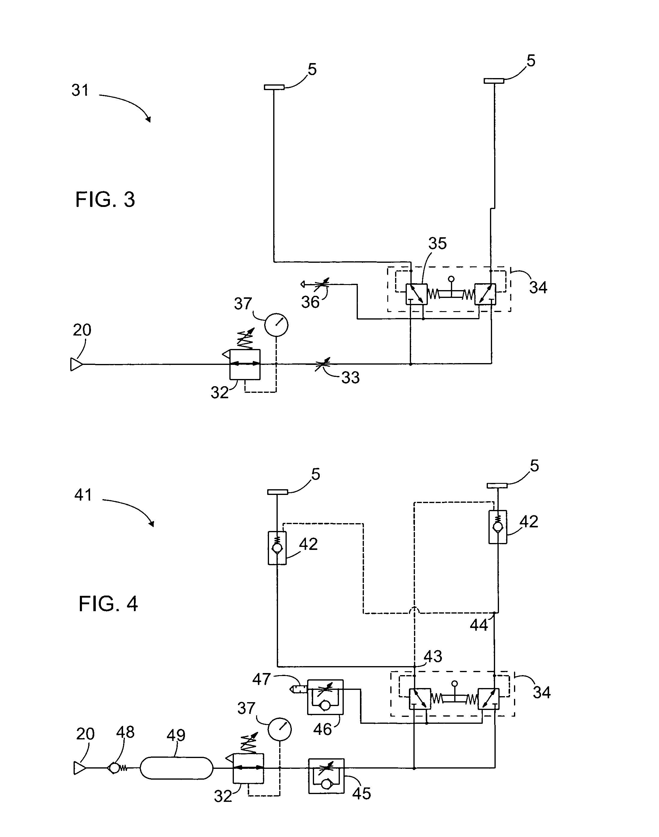
[0045]FIG. 4 illustrates another example of an embodiment 41 of the control means according to the invention; this is actually a variation of the embodiment in FIG. 3. In the embodiment in FIG. 4, the control means 41 also comprises a non-return valve 48 connected to the supply connection 20 to prevent return flow of the pressure medium from the control means 41 to the external source of pressure medium, a pressure medium tank 49 connected to the non-return valve 48 at the supply connection 20, as well as a pressure relief valve 32. A pressure gauge 37 is installed in connection with the pressure relief valve. The non-return valve 48 prevents any over-pressurized pressure medium from flowing from the control means back to the external source of pressure medium 21. The tank 49 functions as a reserve for the pressure medium.
[0046] The embodiment in FIG. 4 also comprises non-return valves 42 connected to the connectors 5 respectively. These non-return valves 42 are connected to the pre...
embodiment 51
[0050]FIG. 5 illustrates a third example of an embodiment of control means according to the invention. This embodiment 51 is intended to function as a retarder and stopper of the rolling movement of a cylindrical object.
[0051] The control means 51 in FIG. 5 has a supply connection 20 to an external source of pressure medium and comprises a pressure relief valve 32 connected to the supply connection 20 to limit the pressure of the pressure medium, a pressure gauge 37 to indicate the pressure limited by the pressure relief valve, and a one-way restrictor valve 52 connected to the pressure relief valve 32 on the side of limited pressure so that it allows free flow of the pressure medium towards the pressure element 3. The one-way restrictor valve 52 may also be functionally connected to the connectors 5 at both ends of the pressure element 3. The connector 5 at the first end of the pressure element may be connected directly to the one-way restrictor valve. The connector 5 at the second...
embodiment 61
[0055]FIG. 6 illustrates a fourth example of an embodiment 61 of the control means according to the invention. The control means 61 is used with three pressure elements (not shown), although the connectors 5 for only one pressure element are shown. Similar to FIG. 5, this embodiment functions as a retarder and stopper of a cylindrical object. The control means 61 has a supply connection 20 to an external source of pressure medium and comprises a non-return valve 48 connected to the supply connection 20, as well as non-return valves 67, 54 specific to the connectors 5. The non-return valves are connected to the connectors 5 to allow the pressure medium to flow out of the pressure element 3 when the pressure of the pressure medium within the pressure element is sufficiently high.
[0056] At least one of the non-return valves 67, 54 specific to the connectors 5 of each pressure element is controllable so that it allows the pressure medium to flow into the pressure element. In practice, t...
PUM
 Abstract
Description
Claims
Application Information