Vehicle ballast system

Inactive Publication Date: 2006-10-05
CHILDS THOMAS +2
View PDF11 Cites 3 Cited by
  • Summary
  • Abstract
  • Description
  • Claims
  • Application Information

AI Technical Summary

Benefits of technology

[0012] The vehicle ballast system of the present invention allows for the easy placement and removal of ballast load when and where desired in the storage area of a vehicle, such as the bed of a truck. The present system allows for convenient and relatively rapid move

Problems solved by technology

As a result, such vehicles are generally unevenly weighted, setting up the possibility of a reduction in traction at the rear end.
In spite of the advances in vehicle drive operation, there remains a substantial portion of vehicles without sufficient load balancing to operate effectively under all conditions.
For example, drivers tasked to conduct snow removal operations, particularly those employing pickup trucks, often do not have sufficient ballast at the rear.
This can reduce traction at the rear end, and generally can reduce handling stability under a variety of road conditions.
However, this does not balance the overloading of the front axle of the truck associated with the attached plow, nor does it improve vehicle handling.
Unfortunately, such loads may not be placed a sufficient distance behind the vehicle's center of gravity to balance the truck effectively.
Moreover, these loads tend to shift when the truck is in use, or they may be insufficient to provide the desired traction, particularly when snowplowing is performed.
Further, the load may

Method used


Image

  • Vehicle ballast system
  • Vehicle ballast system
  • Vehicle ballast system

Examples


Example

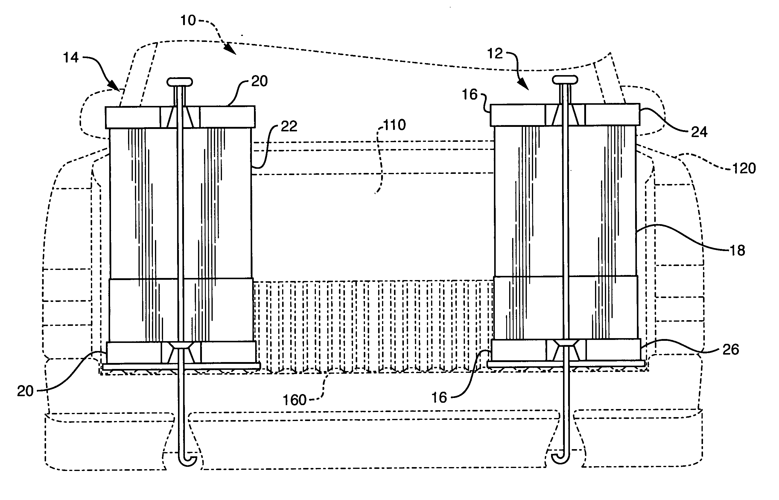
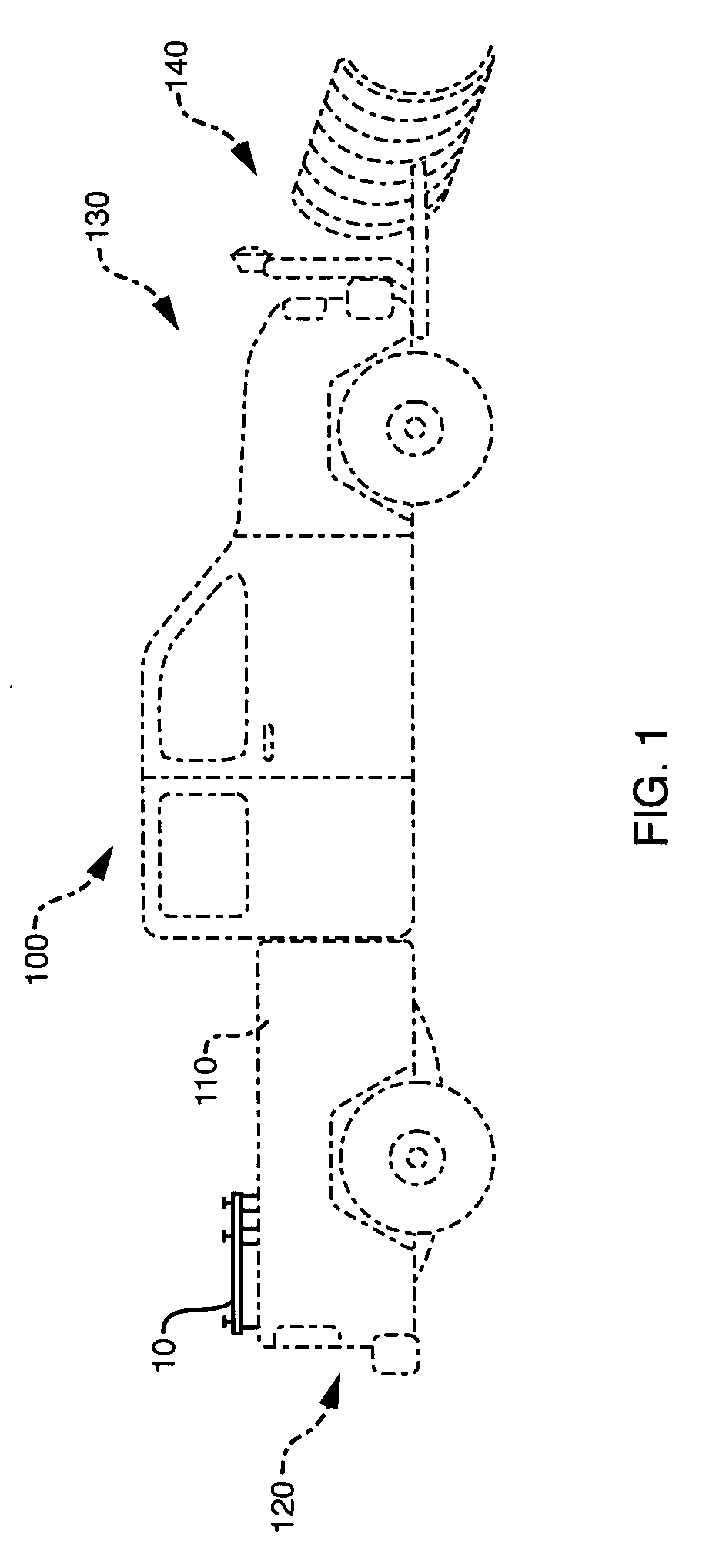
[0019] A vehicle ballast system 10 of the present invention is shown in FIGS. 1-5. In FIG. 1, the vehicle ballast system 10 is shown positioned in a storage compartment (truck bed 110) of a vehicle (truck 100). The vehicle ballast system 10 may be deployed in any of a plurality of locations within the truck bed 110. However, it is preferably positioned at a back end 120 of the truck 100 to counterbalance any opposing weight or load at a front end 130 of the truck, such as the truck's engine (not shown), or a snowplow 140. The vehicle ballast system 10 may vary in dimensions as a function of the available space in the storage compartment, the ballast needed, and / or the material available to provide the ballast portion of the system 10.

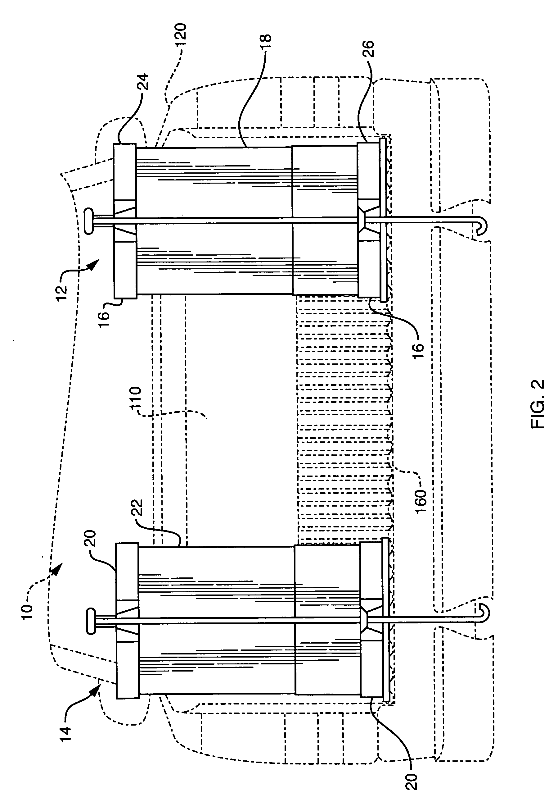
[0020] As illustrated in FIGS. 2-4, the vehicle ballast system 10 preferably includes a first ballast unit 12 and a second ballast unit 14. Alternatively, a single ballast unit may be employed, or more than two ballast units may be employed, dependent ...


PUM


Abstract

A vehicle ballast system for improving the balance of a vehicle. The system is particularly well suited for use in the bed of a pickup truck but is not limited to that deployment. The system includes one or more ballast units. Each ballast unit includes a frame set and a ballast element. The frame set retains the ballast element therein. The ballast element may be one or more concrete blocks. The frame set includes an upper frame and a lower frame. The respective frames are connected together in a manner to contain the ballast element using a front retaining rod and a rear retaining rod is preferably affixable to a bracket secured to the rear of the vehicle. A tether may be removably connected between the upper frame and a securing point of the vehicle. A shock-absorbing lanyard may be employed at the rear of the system as a restraint upon sudden deceleration of the vehicle.

Description

BACKGROUND OF THE INVENTION [0001] 1. Field of the Invention [0002] The present invention relates to systems for improving vehicle balance. The present also relates to such systems configured to improve stability and counterbalance overloaded vehicles axles. More particularly, the present invention relates to a ballasting system installable in the bed of a truck. [0003] 2. Description of the Prior Art [0004] Most vehicles are configured with the engine at the front and storage capacity at the rear. As a result, such vehicles are generally unevenly weighted, setting up the possibility of a reduction in traction at the rear end. In the past, vehicles had rear-wheel drive, and drivers would add load or weight, referred to herein as ballast, at the vehicle rear to counterbalance the front-end loading and improve vehicle traction. Vehicle traction is particularly important when road conditions are less than optimal, such as when covered in snow, ice, or water. Advances in vehicle design ...

Claims


Application Information

Patent Timeline
IPC IPC(8): B60S9/00
CPCB62D49/0628
Inventor CHILDS, THOMASFROEHLICH, GEORGECHILDS, WILLIAM C.
Owner CHILDS THOMAS
Why Eureka
Try Eureka