Electromagnetic actuator and camera blade driving device

a technology of electric actuator and driving device, which is applied in the direction of magnetic circuit rotating parts, magnetic circuit shape/form/construction, instruments, etc., can solve the problems of small size, difficult to stably drive the shutter blade and hold this at a predetermined position, and difficult to sufficiently secure the driving torque generated

Active Publication Date: 2006-10-05
COPAL CO LTD
View PDF13 Cites 4 Cited by
  • Summary
  • Abstract
  • Description
  • Claims
  • Application Information

AI Technical Summary

Benefits of technology

[0016] According to this structure, the protrusion parts are magnetized into N- and S-poles, and hence the protrusion parts can be directed from the inside in the radial direction toward the circular arc surface of the first magnetic-pole part and the circular arc surface of the second magnet

Problems solved by technology

If the electromagnetic actuator is merely reduced in size without changing the conventional structure, themagnetized cylindrical rotor becomes small in size, and it becomes difficult to sufficiently secure a driving torque generated by the rotor during energization and

Method used


Image

  • Electromagnetic actuator and camera blade driving device
  • Electromagnetic actuator and camera blade driving device
  • Electromagnetic actuator and camera blade driving device

Examples


Embodiment Construction

[0029] Embodiments of the present invention will be hereinafter described with reference to the accompanying drawings.

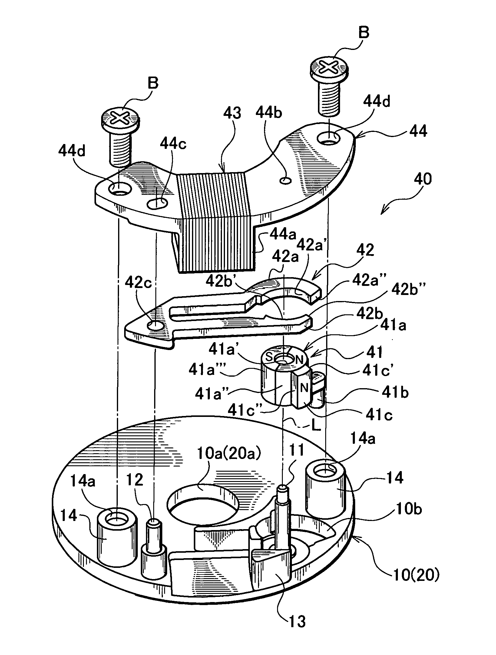
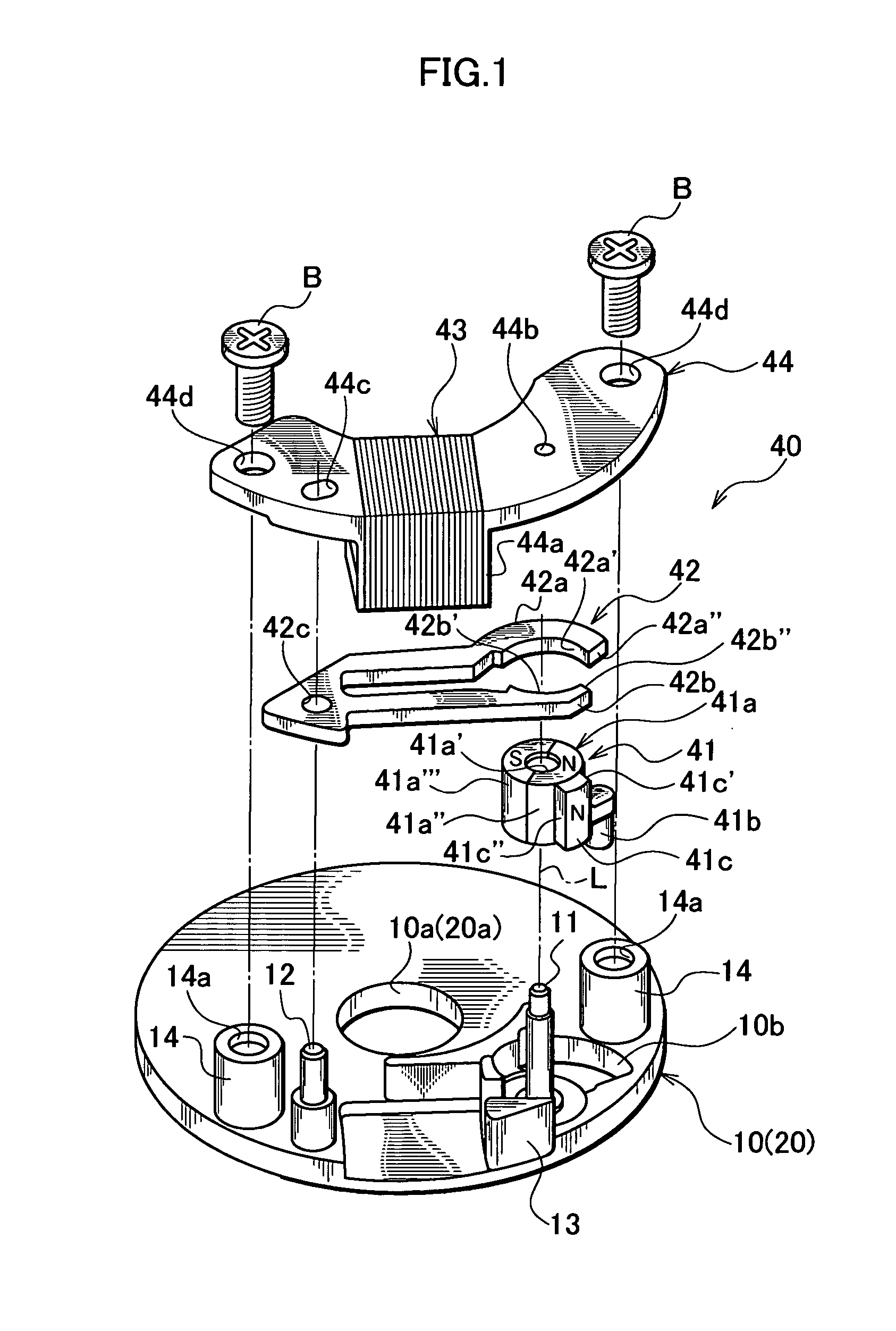
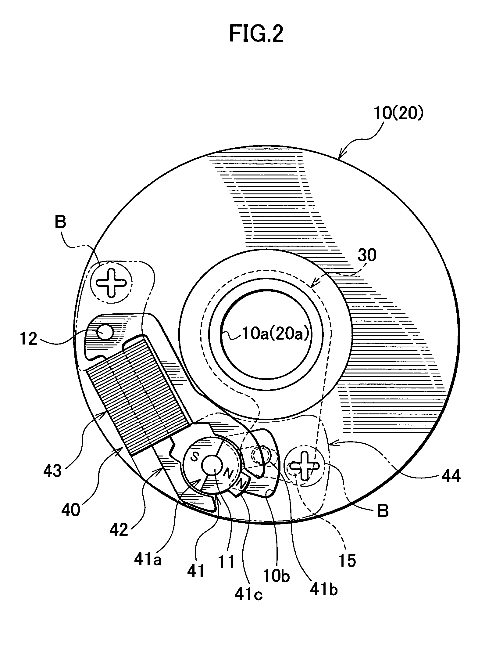
[0030]FIG. 1 to FIG. 6 show an embodiment in which an electromagnetic actuator according to the present invention is applied to a camera blade driving device.

[0031] As shown in FIG. 1 to FIG. 3, the camera blade driving device includes a main plate 10 and a back plate 20 that constitute a base plate having exposure apertures 10a and 20a, a blade member 30 supported by the main plate 10 movably between a position facing the apertures 10a and 20a and a position retreating from the apertures 10a and 20a, and an electromagnetic actuator 40 serving as a driving source that drives the blade member 30.

[0032] As shown in FIG. 1 to FIG. 3, the main plate 10 has a circular exposure aperture 10a, a supporting shaft 11 that rotatably supports a rotor 41 described later, a substantially fan-shaped through-hole 10b, a positioning pin 12 and a positioning projection 13 both of w...


PUM


Abstract

An electromagnetic actuator of the present invention includes a rotor that has a cylindrical outer peripheral surface and that is capable of rotating within a predetermined angular range, a magnetizing coil, and a yoke that has an arcuate surface facing the outer peripheral surface, a first magnetic-pole part, and a second magnetic-pole part. The first and second magnetic-pole parts generate mutually different magnetic poles by energizing the coil. The rotor includes a magnetized rotor part that defines the outer peripheral surface of the rotor and that is magnetized to have different magnetic poles in a circumferential direction, a driving pin that is not magnetized so as to rotate together with the magnetized rotor part, and a protrusion part that is protruded in a radial direction from the outer peripheral surface of the rotor and that faces the first magnetic-pole part or the second magnetic-pole part while being magnetized to have the same magnetic pole as the outer peripheral surface of the rotor. According to this structure, the rotor includes the protrusion part that is protruded from the outer peripheral surface of the magnetized rotor part and that is magnetized, in addition to the magnetized rotor part and the driving pin that is not magnetized. Therefore, the surface of the rotor that faces the yoke and that exerts a magnetic action is increased, and hence a desired maintaining force and a driving torque can be obtained.

Description

BACKGROUND OF THE INVENTION [0001] 1. Field of the Invention [0002] The present invention relates to an electromagnetic actuator that generates a driving force by an electromagnetic force. More specifically, the present invention relates to an electromagnetic actuator that includes a rotor having a magnetized outer peripheral surface and a yoke that forms a magnetic-pole part facing the outer peripheral surface of the rotor and that is used when a blade member of a camera, such as a shutter blade or a diaphragm blade, is driven, and relates to a camera blade driving device using the electromagnetic actuator. [0003] 2. Description of the Related Art [0004] A conventionally known electromagnetic actuator mounted on, for example, a shutter device of a camera includes a cylindrical rotor that is supported rotatably with respect to a base plate having an exposure aperture and that is magnetized into N and S-poles by bisecting its outer peripheral surface in the circumferential direction,...

Claims


Application Information

Patent Timeline
IPC IPC(8): H02K1/22H02K37/14H02K37/12
CPCG03B9/02H02K26/00G03B9/10
Inventor WATANABE, NOBUAKI
Owner COPAL CO LTD
Why Eureka
Try Eureka