Generic radio transmission network for door applications
Inactive Publication Date: 2006-10-05
ALBANY INT CORP
View PDF19 Cites 55 Cited by
Summary
Abstract
Description
Claims
Application Information
AI Technical Summary
This helps you quickly interpret patents by identifying the three key elements:
Problems solved by technology
Method used
Benefits of technology
Benefits of technology
[0020] It is a further object to reduce transmitter repetitions and save battery power, to provide a battery-powered door-opening transceiver unit that eliminates cables, to provide a wirelesscontrol system in order to eliminate wiring, to provide a door-to-door radio communication that eliminates wiring, to provide door unit relay status via a network to a display, and to provide a door to a host computer or concentrator communication.
[0024] According to the present invention there is provided a wirelessradio transmission network wherein the display unit is located within a close proximity of the one or more high-speed doors or at a remote location from the one or more high-speed doors, wherein the one or more mobile radio transceivers and the one or more stationary radio transceivers include light emitting diodes (LEDs) to indicate operation activity to a user, wherein the unique identifiers of the one or more stationary and mobile radio transceivers are radio frequency (RF) identifiers or infrared (IR) identifiers, wherein the unique identifiers of the one or more stationary and mobile radio transceivers are located on or in their respective transceivers, wherein the network operates in a plurality of bands, wherein the plurality of bands are six, one band for common short open / close communication, one band used as a backup, and the other four bands reserved for special usage, such as communication with a service representative and wherein the one or more mobile radio transceivers each adjust their signal sensitivity level in order to minimize interference effects.
Problems solved by technology
This configuration is complex, bulky, expensive and consumes excessive amounts of battery power due to transmitter repetitions.
Method used
Image
Click on the blue label to locate the original text in one second.
Reading with bidirectional positioning of images and text.
Examples
first embodiment
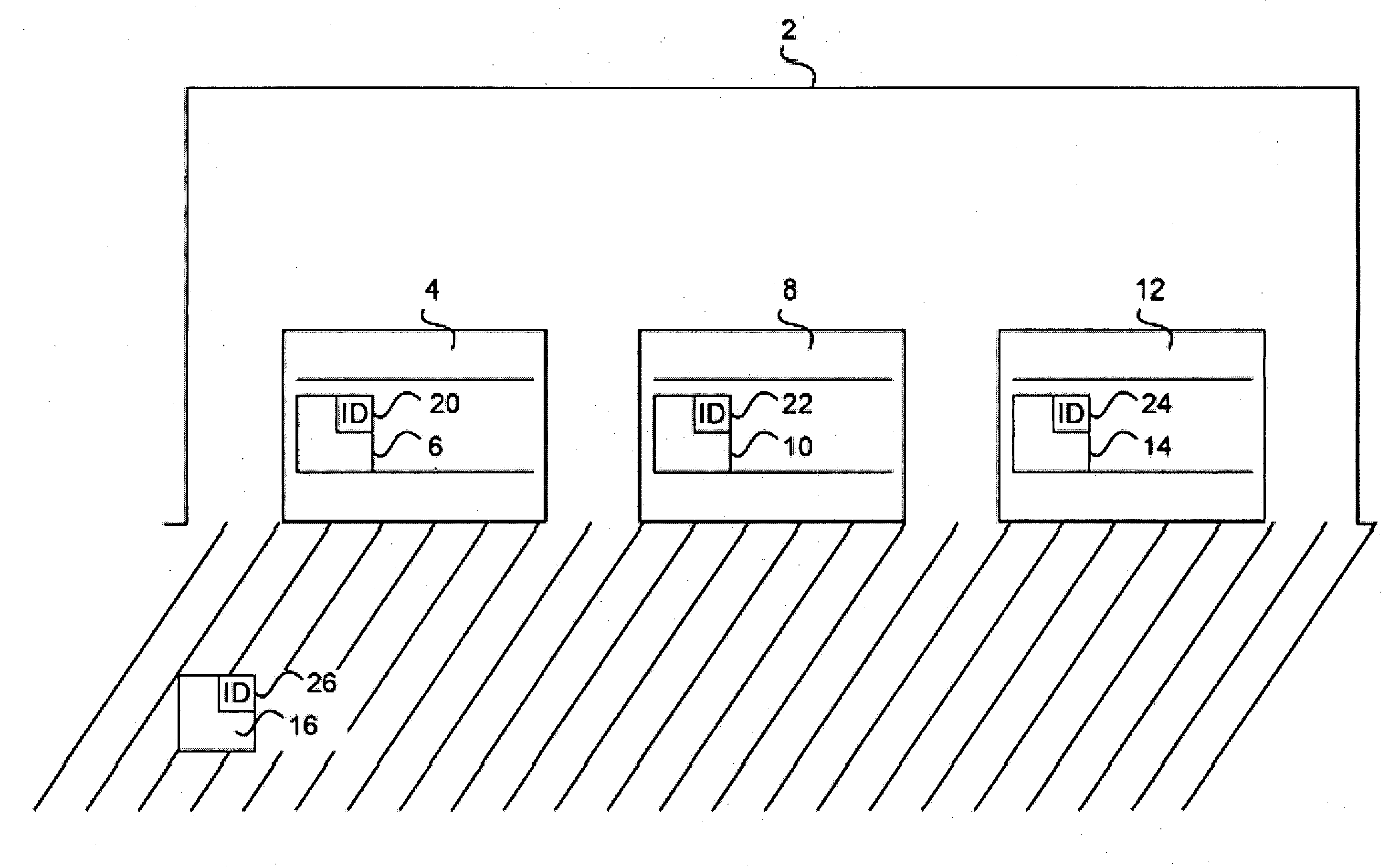
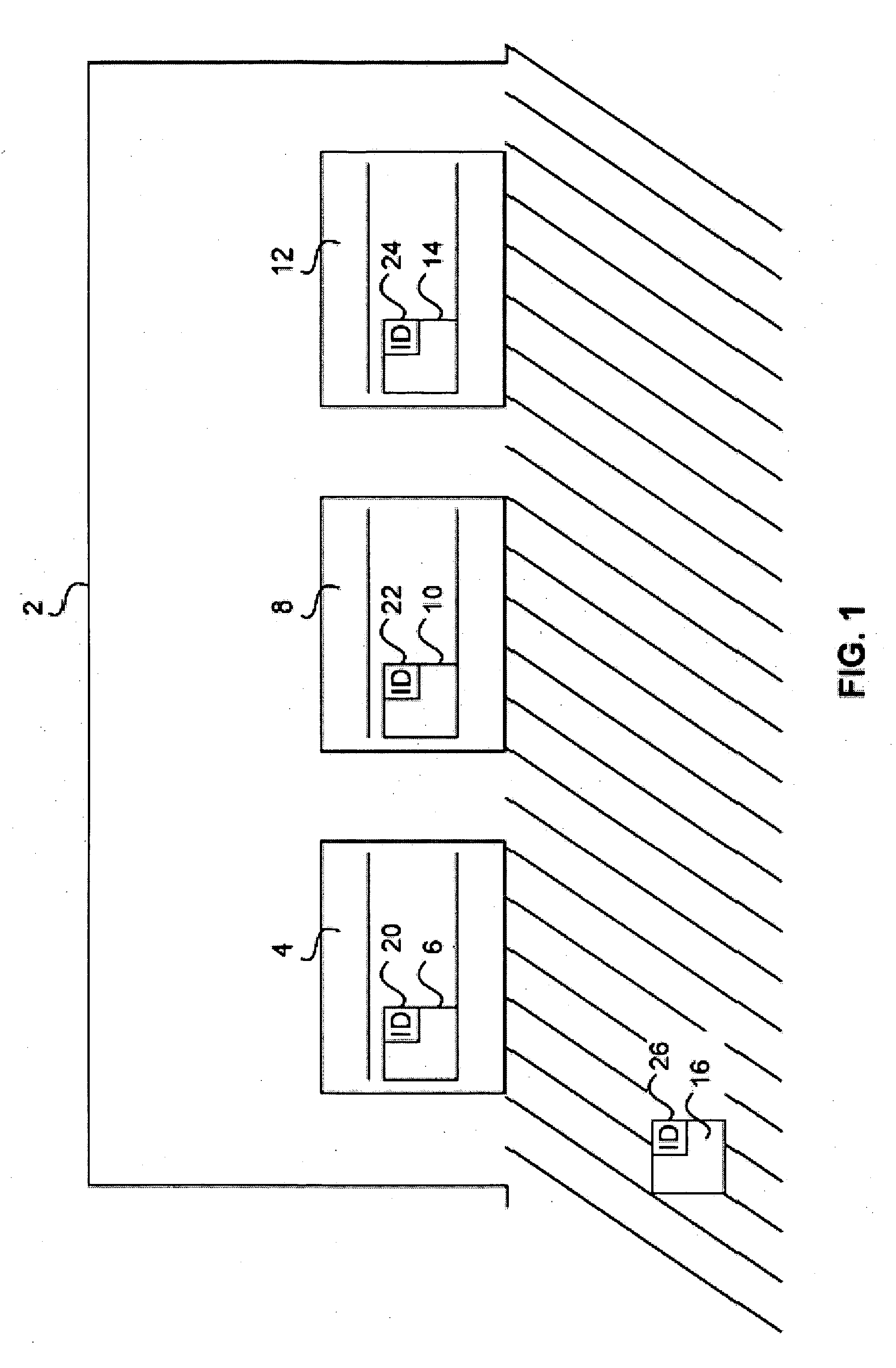
[0035] A first embodiment of the radio transmission network according to the present invention is described with reference to FIG. 1. FIG. 1 illustrates a system or radio transmission network where stationary transceivers are mounted on a plurality of respective doors.
[0036] In this example, as shown in FIG. 1, a building 2 comprises three doors 4, 8, 12. Stationary transceivers 6, 10, 14 are mounted on each of the three doors 4, 8, 12, respectively. Each of the stationary transceivers 6, 10, 14 incorporates identifiers 20, 22, 24, respectively. When a mobile transmitter 16 approaches the vicinity of door 4, door 4 opens automatically.
[0037] More specifically, a worker using a forklift (not shown) carries a hand-held mobile transceiver 16 or the mobile transceiver 16 is mounted on the forklift itself. Once the forklift carrying the mobile transceiver 16 is located at a predetermined distance away from the door 4, the mobile transceiver 16 triggers the stationary transceiver 6 loca...
second embodiment
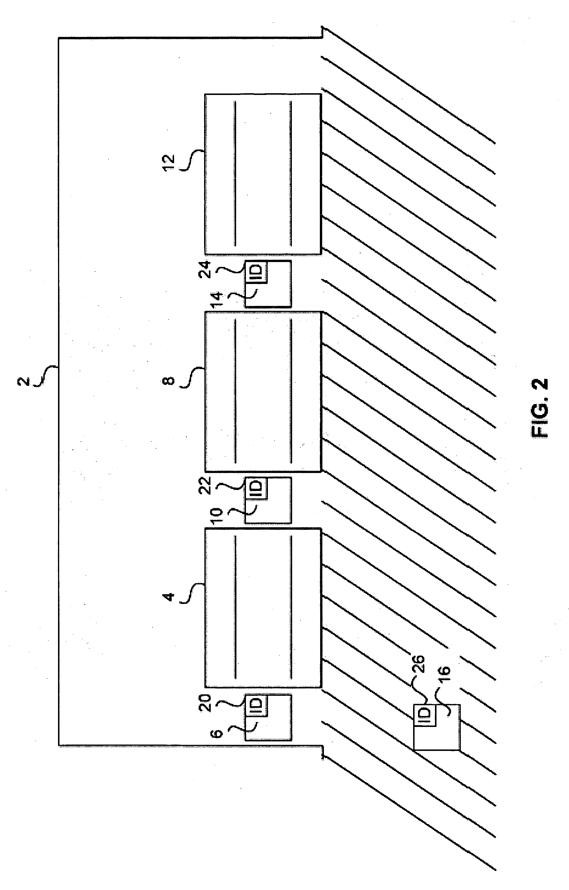
[0041] A second embodiment of the radio transmission network according to the present invention is described with reference to FIG. 2. FIG. 2 illustrates a system or radio transmission network where the stationary transceivers are mounted next to the plurality of doors.
[0042] The reference numerals of FIG. 2 denote the same elements as in FIG. 1. The difference between FIGS. 1 and 2 is that the stationary transceivers 6, 10, 14 are located next to the doors 4, 8, 12, respectively (as in FIG. 2), for example, on a wall, instead of being mounted directly on the doors 4, 8, 12 (as in FIG. 1).
[0043] Again, for instance, if a forklift carrying the mobile transceiver 16 is located at a predetermined distance away from the door 4, the mobile transceiver 16 triggers the stationary transceiver 6 located next to the door 4. Once the stationary transceiver 6 receives a trigger signal, the door 4 automatically opens at a rapid speed in order to allow a worker on the forklift to enter through ...
PUM
Abstract
A wirelessradio transmission network comprising: one or more high-speed doors; one or more stationary radio transceivers, each of the one or more stationary radio transceivers having a unique identifier; and one or more mobile radio transceivers, each of the one or more mobile radio transceivers having a unique identifier; wherein when a mobile transceiver approaches within a predetermined distance of a stationary transceiver and when the unique identifier of the stationary transceiver verifies that the unique identifier of the mobile transceiver is an acceptable identifier, a high-speed door is triggered to open.
Description
BACKGROUND OF THE INVENTION [0001] 1. Field of the Invention [0002] The present invention relates to a radio unit or a radio transceiver that is used in door applications. Specifically, the present invention comprises a plurality of stationary and mobile radio transceivers that are triggered to facilitate the rapid opening and closing of doors. [0003] 2. Description of the Related Art [0004] There has been a great need to use rapidly moving doors in buildings for industrial use. This applies to indoor openings as well as to external walls, where one or more doors provide shielding between different activities or prevent drafts and heat losses. [0005] Presently, rolling doors with flexible door leaves are used for this purpose, but also more rigid constructions like slatted doors with polymeric or metallic lamellae are used. These doors are rolled up on an overhead drive cylinder and can be provided with additional elements like a weight balance system, tensioning system, windows or ...
Claims
Application Information
Patent Timeline
Application Date:The date an application was filed.
Publication Date:The date a patent or application was officially published.
First Publication Date:The earliest publication date of a patent with the same application number.
Issue Date:Publication date of the patent grant document.
PCT Entry Date:The Entry date of PCT National Phase.
Estimated Expiry Date:The statutory expiry date of a patent right according to the Patent Law, and it is the longest term of protection that the patent right can achieve without the termination of the patent right due to other reasons(Term extension factor has been taken into account ).
Invalid Date:Actual expiry date is based on effective date or publication date of legal transaction data of invalid patent.

