Fluid-gauging systems

a technology of fluid gauges and fluid gauges, applied in liquid/fluent solid measurement, instruments, machines/engines, etc., can solve the problems of inability to provide a secondary gauge system, inability to fit such a system to modern composite wings, and inability to provide such a system

Active Publication Date: 2006-10-05
SMITHS GRP PLC
View PDF6 Cites 8 Cited by
  • Summary
  • Abstract
  • Description
  • Claims
  • Application Information

AI Technical Summary

Problems solved by technology

It is undesirable to have to provide a secondary gauging system because of the additional cost and weight of such systems, and the difficulty of fitting such a system to modern composite wings

Method used


Image

  • Fluid-gauging systems
  • Fluid-gauging systems

Examples


Embodiment Construction

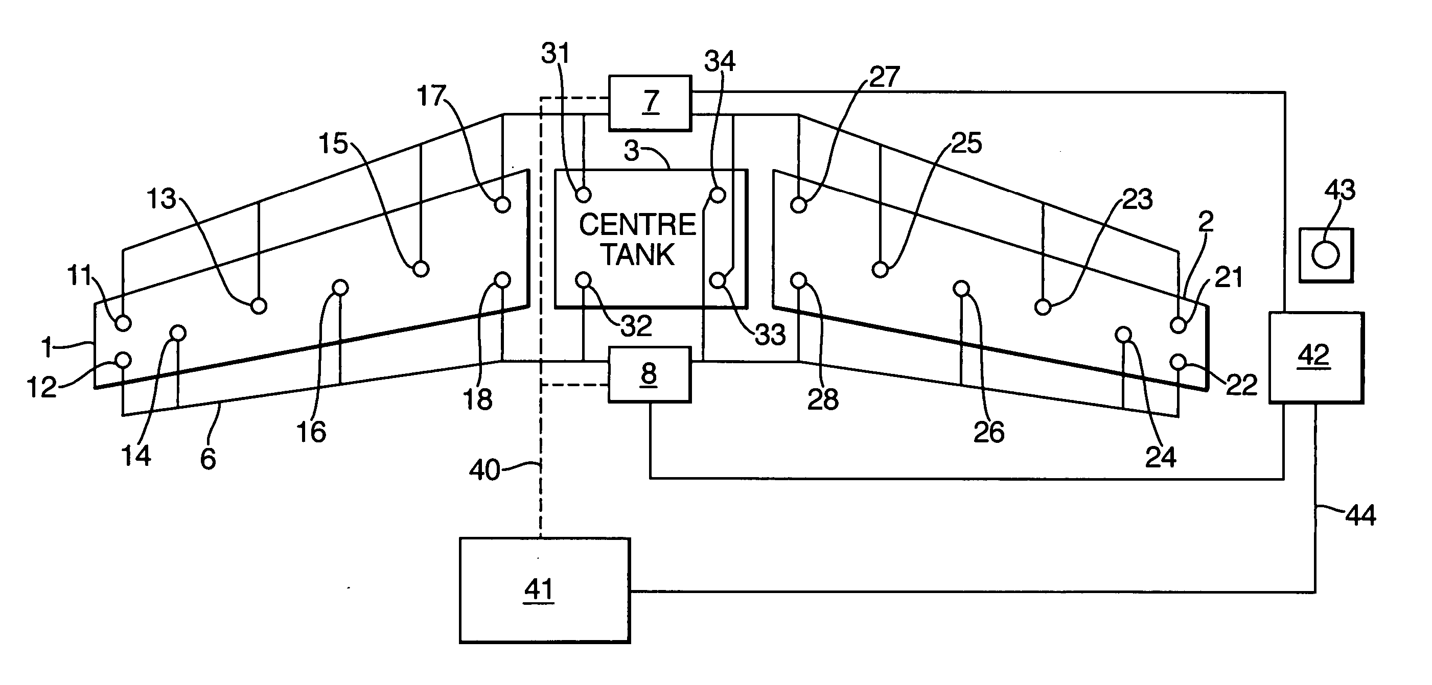
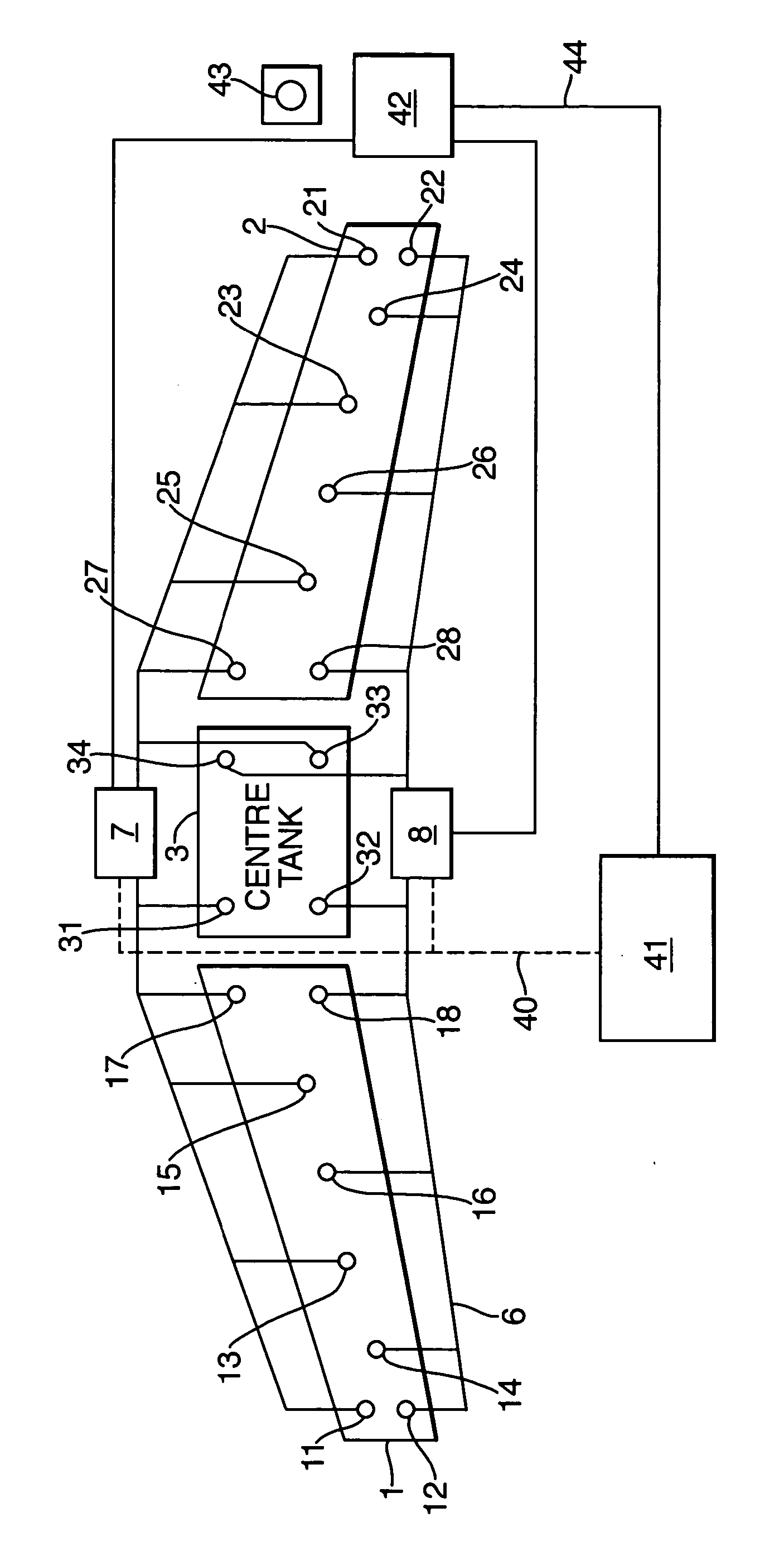
[0013] The system includes two wing tanks 1 and 2 and a centre tank 3. The wing tanks 1 and 2 each include eight fuel height gauging probes or sensors 11 to 18 and 21 to 28 respectively, each of a conventional kind. The centre tank 3 has four sensors 31 to 34. A first group of odd-numbered sensors 11, 13, 15, 17, 21, 23, 25, 27, 31 and 33 are connected by wiring 5 to a first fuel-gauging computer or processor 7. A second group of even-numbered sensors 12, 14, 16, 18, 22, 24, 26, 28, 32 and 34 are connected by wiring 6 to a second fuel-gauging computer or processor 8, independent from the first processor 7. The processors 7 and 8 are each programmed to provide an output indication indicative of fuel quantity from a suitable fuel-gauging algorithm, pre-programmed with information about the shape of the tanks 1, 2 and 3 and from the height information from the sensors 11 to 18, 21 to 28 and 31 to 34 connected with the processors. The quantity information may be in the form of fuel volu...


PUM


Abstract

An aircraft fuel-gauging system has multiple gauging sensors in each tank divided into two groups. Each group of sensors connects with a respective processor. The processors are linked to provide a display in the cockpit to give an indication of fuel quantity derived from all the sensors. The two processors also provide separate, nominally-identical display indications of fuel quantity on a refuel panel on the exterior of the aircraft. The refueller can compare these two separate quantity indications with the flow meter in the fuel dispenser to confirm that the correct quantity has been dispensed.

Description

BACKGROUND OF THE INVENTION [0001] This invention relates to fluid-gauging systems and methods. [0002] The invention is more particularly, but not exclusively, concerned with aircraft fuel-gauging systems. [0003] Aircraft include fuel-gauging systems to measure the quantity of fuel present in the fuel tanks. There are usually several fuel tanks, often located in the wings, each tank usually having several sensors or probes to measure the height of fuel present. With knowledge of the shape of the tank and the height of fuel at several different locations, the system can compute the volume of fuel in each tank. The number of probes needed depends on the pitch and roll angles likely to be experienced by the aircraft during flight. The gauging probes may be of the capacitive kind, where the capacitance of the probe varies with height of fuel. Alternatively, the probes may be of the ultrasonic kind, where the height is calculated from time for a pulse of acoustic energy to travel from an...

Claims


Application Information

Patent Timeline
IPC IPC(8): G08B21/00G01F23/00G01F25/00
CPCB64D37/00G01F25/0084G01F23/802G01F23/26G01F23/296G01F23/80
Inventor DAVIS, ANDREW
Owner SMITHS GRP PLC
Why Eureka
Try Eureka