Reconfigurable plasma antenna with interconnected gas enclosures

a technology of interconnection and gas enclosure, applied in the field of reconfiguration, can solve the problems of inability to hermetically seal, inability to reconfigure into other conductive arrangements, inability to reconfigure into flexible arrangements, etc., and achieve the effect of high flexibility, without cost and complexity

Inactive Publication Date: 2006-10-05
WSOU INVESTMENTS LLC +1
View PDF10 Cites 15 Cited by
  • Summary
  • Abstract
  • Description
  • Claims
  • Application Information

AI Technical Summary

Benefits of technology

[0013] Advantageously, the illustrative embodiment provides a reconfigurable arrangement of conductive antenna elements. In this embodiment, arbitrary two-dimensional conductive patterns can be programmed by activating particular ones of the enclosures into their electrically conductive plasma states. Accordingly, a high degree of flexibility is provided but without the cost and complexity commonly associated with semiconductor-based arrangements.

Problems solved by technology

A drawback of this type of arrangement is that the enclosure shape is fixed and thus cannot be reconfigured into other conductive arrangements.
Flexible structures are not practical in such arrangements because they usually cannot be hermetically sealed at reasonable cost, when long lifetimes are desired.
However, electromagnets have the disadvantage of being bulky and represent conductive obstacles.
They are therefore not suitable for use in antenna applications that depend on free propagation of electromagnetic waves.
Such techniques are disclosed in U.S. Pat. No. 6,567,046, issued May 20, 2003 to Taylor et al. and entitled “Reconfigurable Antenna,” and U.S. Pat. No. 6,597,327, issued Jul. 22, 2003, to Kanamaluru et al. and entitled “Reconfigurable Adaptive Wideband Antenna.” These semiconductor-based arrangements, however, are unduly complex, and require costly components.

Method used


Image

  • Reconfigurable plasma antenna with interconnected gas enclosures
  • Reconfigurable plasma antenna with interconnected gas enclosures
  • Reconfigurable plasma antenna with interconnected gas enclosures

Examples


Embodiment Construction

[0019] The present invention will be illustrated herein in the context of example reconfigurable plasma antenna arrangements. It should be understood, however, that the present invention, is not limited to the particular arrangements shown and described. The techniques of the present invention are more generally suitable for use in any antenna application in which antenna operation can be enhanced or facilitated through plasma-based control of antenna conductive elements.

[0020] The term “antenna” as used herein is intended to be construed broadly so as to encompass, by way of example and without limitation, any arrangement of conductive elements configured to radiate signals, to receive signals, or both.

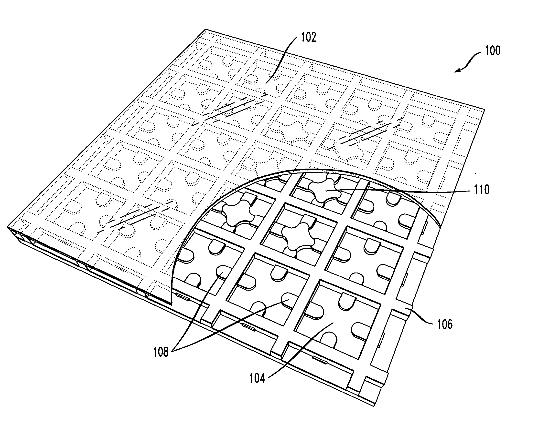
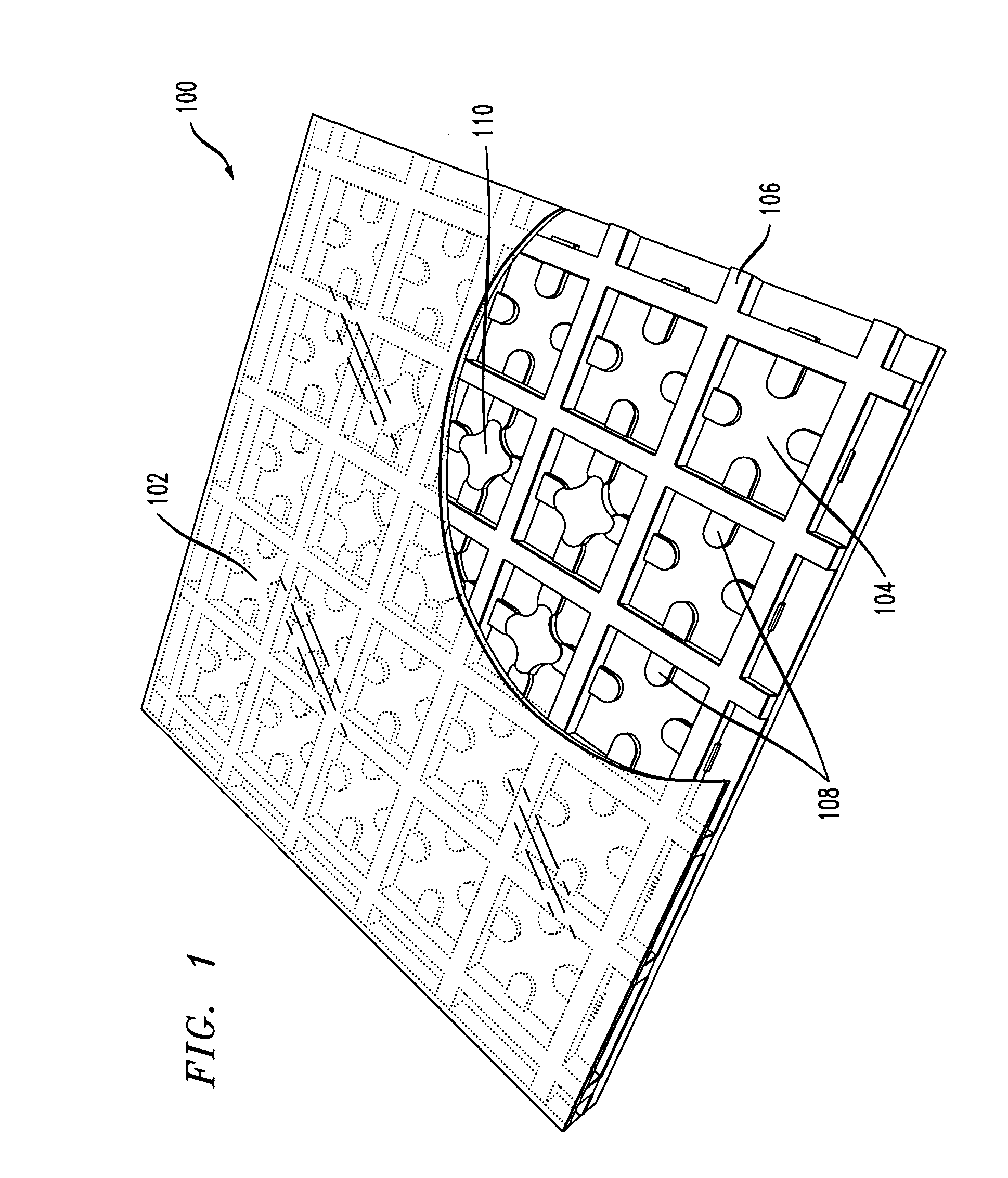
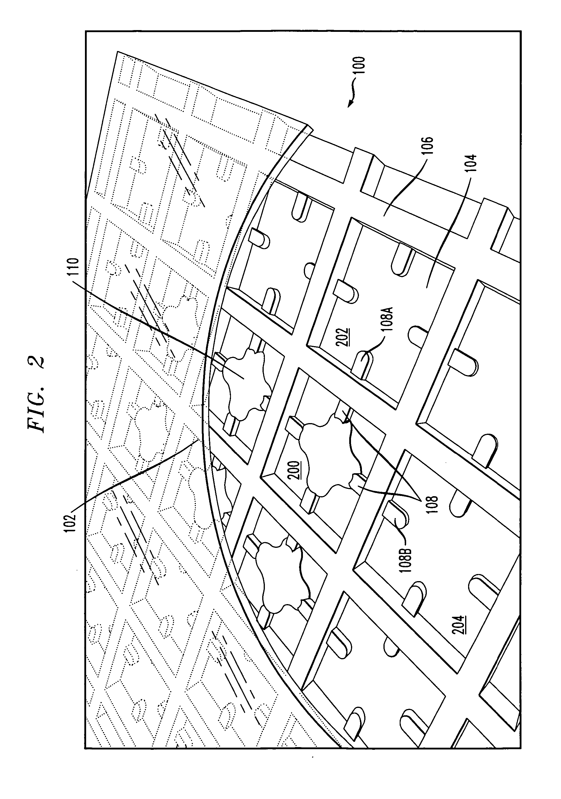
[0021] Referring initially to FIG. 1, a portion of a reconfigurable antenna in an illustrative embodiment of the invention is shown. The particular portion of the reconfigurable antenna shown is a reconfigurable aperture 100 which comprises an array of interconnected gas enclosures...


PUM


Abstract

A reconfigurable antenna comprises an array of interconnected gas enclosures, each of the enclosures being controllable between at least a first state in which gas within the enclosure is substantially non-conducting and a second state in which the gas within the enclosure forms an electrically conductive plasma. At least one pair of adjacent enclosures in the array is arranged such that configuring the pair of enclosures in the second state results in an electrical connection, between a first electrode associated with one of the enclosures of the pair and a second electrode associated with the other enclosure of the pair, through electrically conductive plasma of at least one of the enclosures of the pair. The reconfigurable antenna in an illustrative embodiment is operable in a plurality of different modes of operation by altering, from mode to mode, which of the enclosures are configured in the first state and which of the enclosures are configured in the second state.

Description

FIELD OF THE INVENTION [0001] The present invention relates generally to antennas, and more particularly to antennas which utilize plasma to allow the antenna to be controllable for operation in a variety of different configurations. BACKGROUND OF THE INVENTION [0002] A variety of plasma antennas are known in the art. One type of plasma antenna, from Markland Technologies Inc. of Fredericksburg, Va., utilizes ionized gas enclosed in a tube or other enclosure as an antenna conducting element. In an arrangement of this type, electrodes are typically located at opposite ends of the hermetically sealed enclosure. Electrical discharge from the electrodes ionizes and excites the gas from a non-conductive gaseous state into an electrically conductive plasma state. The enclosure is formed in a particular fixed shape to provide the desired antenna configuration, such as a parabolic reflector configuration. A drawback of this type of arrangement is that the enclosure shape is fixed and thus c...

Claims


Application Information

Patent Timeline
Patent Type & Authority Applications(United States)
IPC IPC(8): H01Q15/02
CPCH01Q1/366
Inventor METZ, CARSTEN
Owner WSOU INVESTMENTS LLC
Why Eureka
Try Eureka