
Thin film magnetic head and magnetic recording apparatus

a technology of magnetic recording apparatus and thin film, which is applied in the direction of heads with metal sheet cores, data recording, instruments, etc., can solve the problem that the front end portion of the magnetic pole layer is not easily magnetized in a direction, and achieve the effect of increasing the strength of the perpendicular magnetic field

Inactive Publication Date: 2006-10-05
TDK CORPARATION
View PDF32 Cites 8 Cited by
  • Summary
  • Abstract
  • Description
  • Claims
  • Application Information

AI Technical Summary

Benefits of technology

[0009] The present invention has been achieved in consideration of such problems and its object is to provide a thin film magnetic head and a magnetic recording apparatus realizing the gradient and strength of a perpendicular magnetic field increased as much as possible.
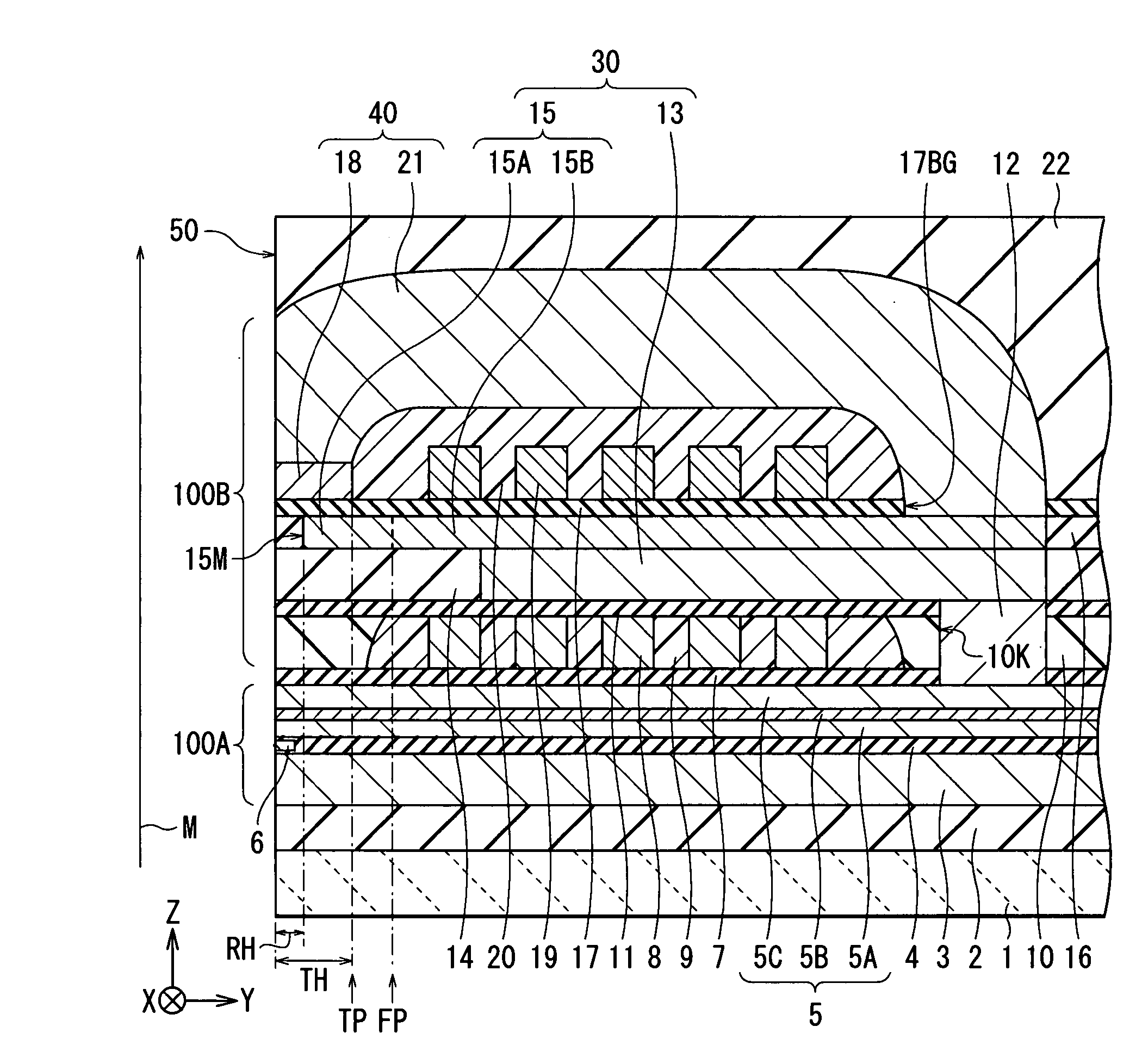
[0016] In the thin film magnetic head and the magnetic recording apparatus according to the present invention, the overlap range in which the magnetic pole layer and the magnetic shield layer overlap one another is small on the basis of the structural feature that the magnetic pole layer recedes from the magnetic shield layer. Consequently, the amount of magnetic flux emitted from the magnetic pole layer toward a recording medium increases relatively, and the amount of magnetic flux leaked from the magnetic pole layer to the magnetic shield layer decreases relatively. Therefore, the gradient and the strength of a perpendicular magnetic field can be increased as much as possible.

Problems solved by technology

In this case, firstly, a front end portion of the magnetic pole layer is not easily magnetized in a direction largely deviated from the perpendicular direction (the direction from the magnetic pole layer toward a recording medium) due to the existence of the magnetic shield layer.

Method used


Image

  • Thin film magnetic head and magnetic recording apparatus
  • Thin film magnetic head and magnetic recording apparatus
  • Thin film magnetic head and magnetic recording apparatus

Examples


Embodiment Construction

[0032] An embodiment of the invention will be described in detail hereinbelow with reference to the drawings.

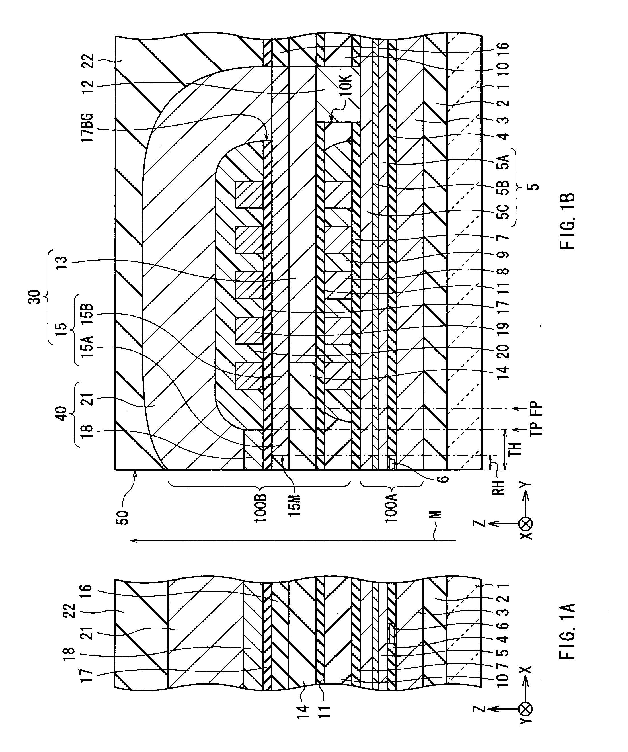
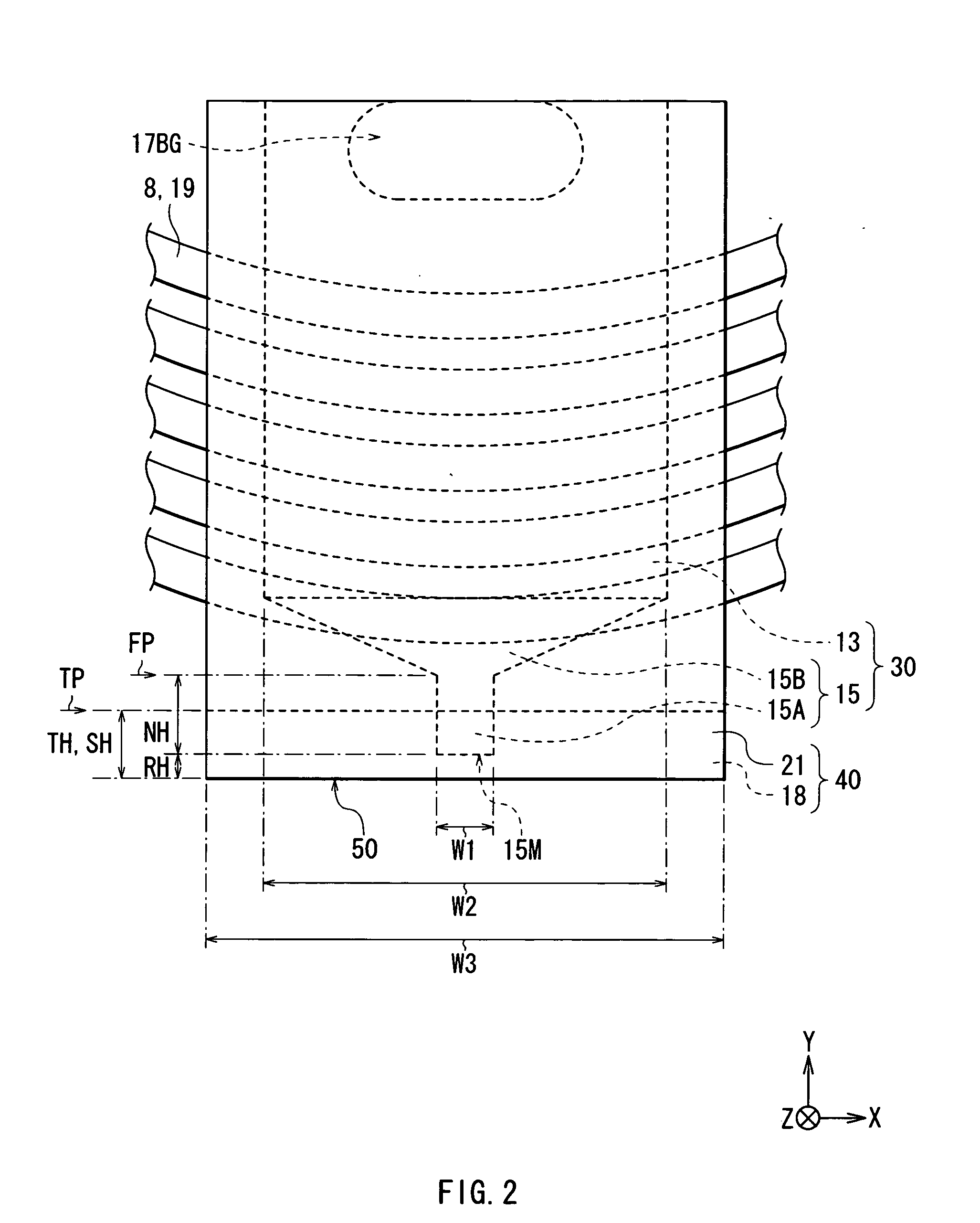
[0033] First, the configuration of a thin film magnetic head according to an embodiment of the invention will be described with reference to FIGS. 1A and 1B to FIG. 3. FIGS. 1A and 1B to FIG. 3 show a configuration of a thin film magnetic head. FIGS. 1A and 1B show a general sectional configuration. FIG. 2 shows a plan view configuration (a plan view configuration seen from the Z-axis direction) of the main part of the thin film magnetic head. FIG. 3 shows a plan view configuration (a plan view configuration seen from the Y-axis direction) of an end surface 15M of a main magnetic pole layer 15. FIG. 1A shows a sectional configuration parallel to an air bearing surface 50 (a sectional configuration along an XZ plane) and FIG. 1B shows a sectional configuration perpendicular to the air bearing surface 50 (a sectional configuration along a YZ plane). An upward arrow M shown in ...


PUM

PropertyMeasurementUnit
thicknessaaaaaaaaaa
thicknessaaaaaaaaaa
thicknessaaaaaaaaaa

Abstract

The present invention provides a thin film magnetic head realizing the gradient and the strength of a perpendicular magnetic field increased as much as possible. A main magnetic pole layer is made recede from a write shield layer. As compared with the case where the magnetic pole layer is not receded from the write shield layer, an overlap range in which the main magnetic pole layer and the write shield layer are overlapped one another is smaller. Accordingly, the amount of magnetic flux emitted from the main magnetic pole layer toward a recording medium relatively increases, and the amount of magnetic flux leaked from the main magnetic pole layer to the write shield layer relatively decreases.

Description

BACKGROUND OF THE INVENTION [0001] 1. Field of the Invention [0002] The present invention relates to a thin film magnetic head having at least an inductive magnetic transducer for recording and a magnetic recording apparatus on which the thin film magnetic head is mounted. [0003] 2. Description of the Related Art [0004] In recent years, in association with increase in areal density of a magnetic recording medium (hereinbelow, simply called “recording medium”) such as a hard disk, improvement in performance of a thin film magnetic head to be mounted on a magnetic recording apparatus such as a hard disk drive (HDD) is demanded. Known recording methods of a thin film magnetic head are, for example, a longitudinal recording method in which the orientation of a signal magnetic field is set to an in-plane direction (longitudinal direction) of a recording medium and a perpendicular recording method in which the orientation of a signal magnetic field is set to a direction orthogonal to the ...

Claims


Application Information

Patent Timeline
Patent Type & Authority Applications(United States)
IPC IPC(8): G11B5/147
CPCG11B5/1278G11B5/3136G11B5/3116
Inventor TAGAMI, KATSUMICHIITO, YUJIHIROSE, MASARUMAEDA, TOSHIAKINISHIO, NOBUTAKA
Owner TDK CORPARATION
Learn More