Illuminator for emitting at least two lights having directivity and display apparatus using same
a technology of directivity and illumination, applied in the field of illumination, can solve the problems of low resolution of each image, difficult manufacture of display apparatus, and inability to display images having a satisfactory image quality, and achieve the effect of simple structur
- Summary
- Abstract
- Description
- Claims
- Application Information
AI Technical Summary
Benefits of technology
Problems solved by technology
Method used
Image

Examples
first embodiment
[0081]FIG. 1 to FIG. 7 show the first embodiment of the present invention. An example where an illuminator according to the present invention is applied to a display apparatus for performing three-dimensional display, will be explained.
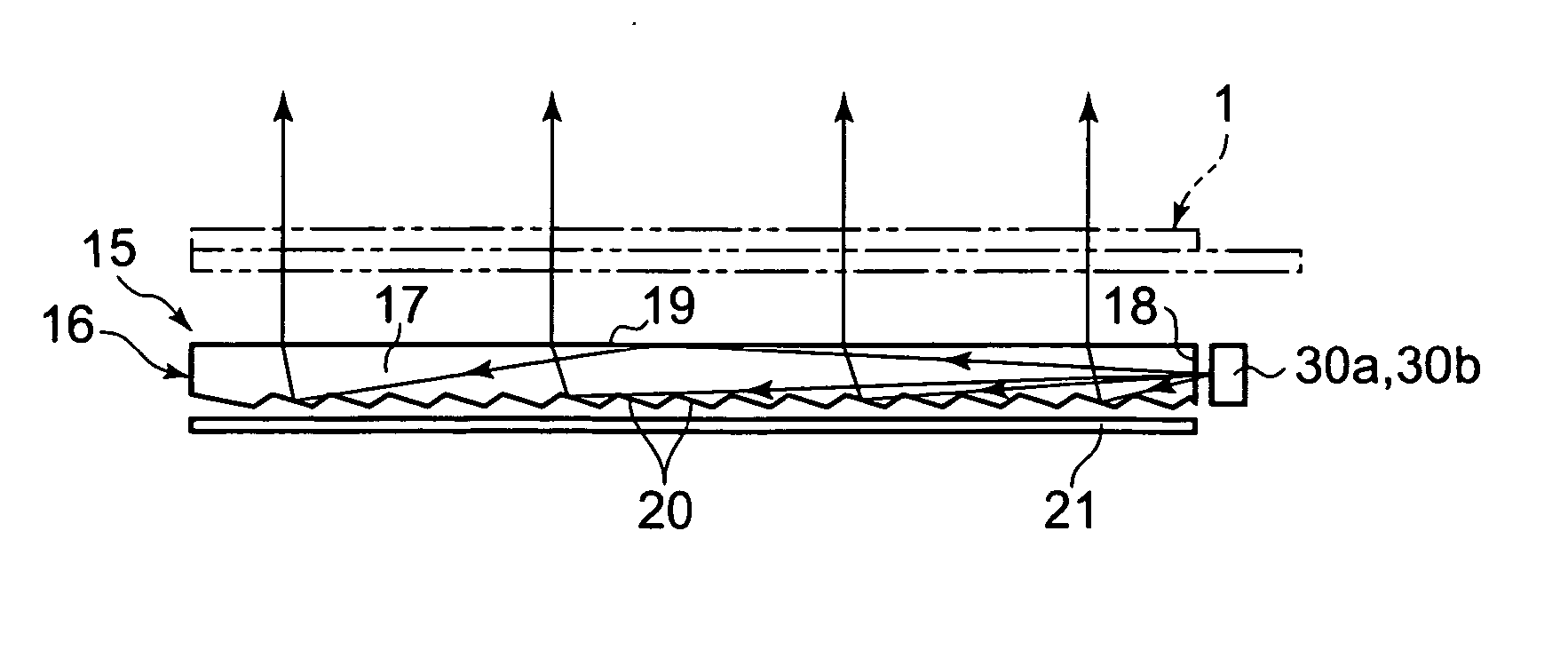
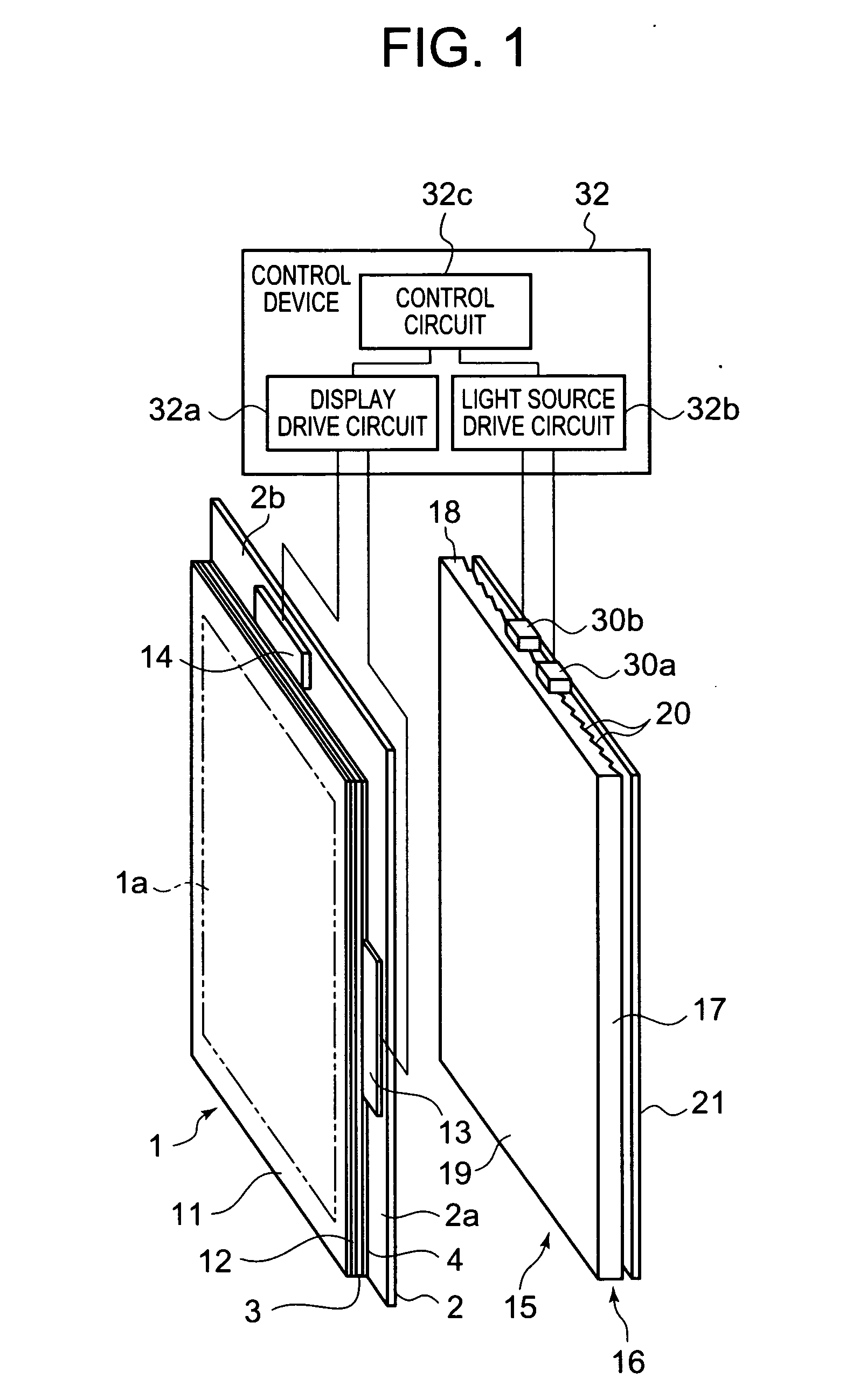
[0082] As shown in FIG. 1, the present display apparatus comprises a display area 1a on which a plurality of pixels (unillustrated) are arranged in a matrix, a liquid crystal display panel 1 on which at least one image is displayed by the plurality of pixels each supplied with a display signal corresponding to image data for displaying an image, an illuminator 15 disposed behind the back surface of the liquid crystal display panel 1 counter to the observation side, and a control device 32 for controlling the display by the liquid crystal display panel 1.
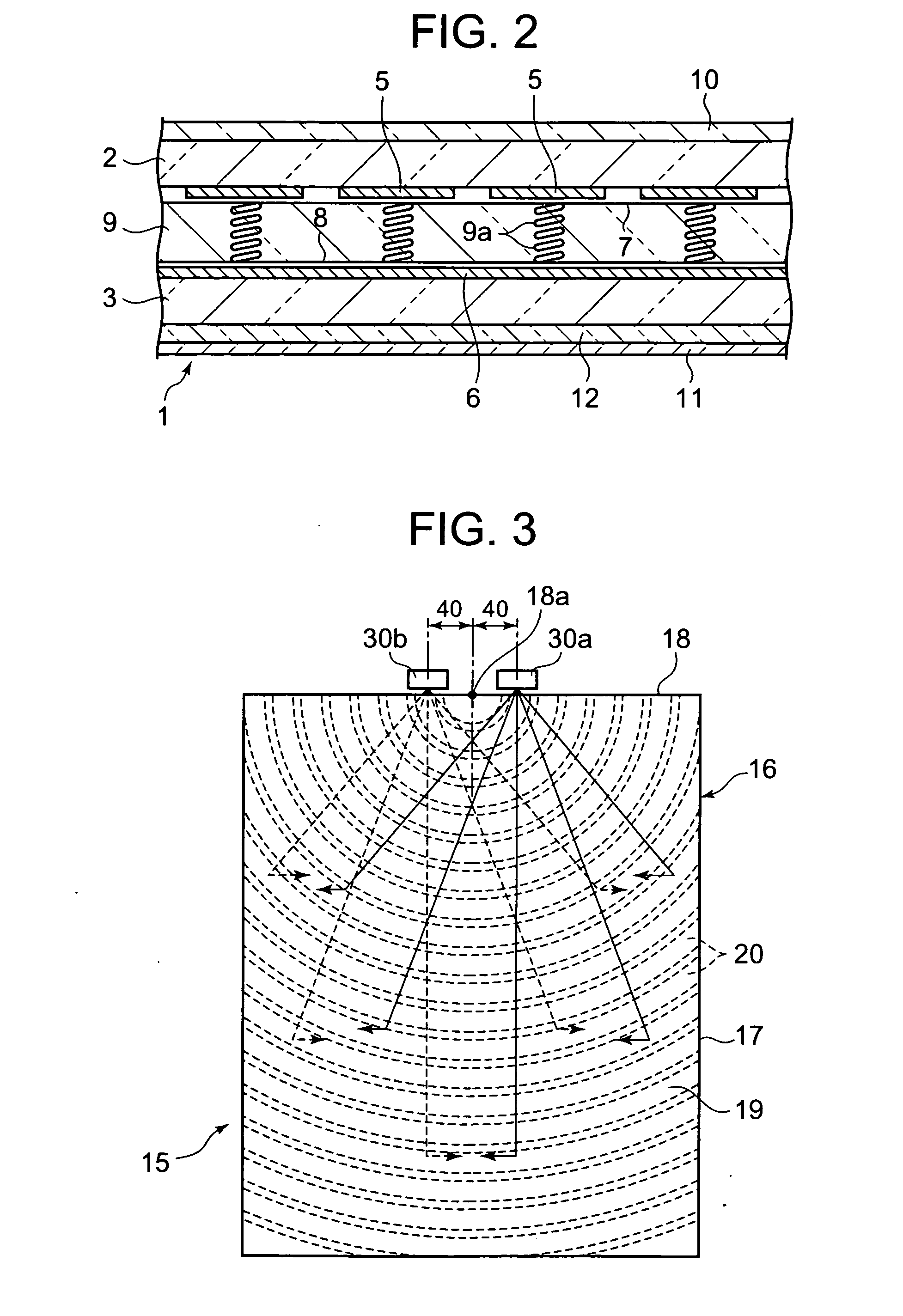
[0083]FIG. 2 is a cross-sectional view of one portion of the liquid crystal display panel 1. The liquid crystal display panel 1 comprises a pair of transparent substrates 2 and 3 jointed to each othe...
second embodiment
[0113]FIG. 8 and FIG. 9 show the second embodiment of the present invention. FIG. 8 is a front elevation of an illuminator, disposed so as to face a surface of the liquid crystal display panel 1 opposite to the observation side, as seen from in front of the illuminator's light exit surface. FIG. 9 is a cross sectional view of the illuminator.
[0114] The light direction changing member 16 of the second embodiment is different from that of the first embodiment, but the other components are the same. Therefore, the same components will be denoted by the same reference numerals, and explanation for such components will be omitted.
[0115] An illuminator 115 according to the present embodiment comprises a light guide plate 22, a prism sheet 27 disposed at the light exit side of the light guide plate 22, and first and second light emitting elements 30a and 30b. The light guide plate 22 is made of plate-like transparent material such as acrylic resin plate. Among the surrounding four end su...
third embodiment
[0124]FIG. 10 and FIG. 11 show the third embodiment of the present invention. FIG. 10 is a front elevation of an illuminator, disposed so as to face a surface of the liquid crystal display panel 1 opposite to the observation side, as seen from in front of the illuminator's light exit surface. FIG. 11 is a distribution graph of the light intensity of light emitted from the illuminator according to the third embodiment. According to the third embodiment, a third light emitting element is additionally included in the structure of first embodiment, and the other components are the same as those of the first embodiment. Thus, the same components will be denoted by the same reference numerals, and explanation for such components will be omitted.
[0125] According to the present embodiment, the illuminator 15 according to the first embodiment further comprises a third light emitting element 31, which is disposed between the first and second light emitting element 30a and 30b so as to face t...
PUM
 Abstract
Description
Claims
Application Information
 - Generate Ideas
- Intellectual Property
- Life Sciences
- Materials
- Tech Scout
- Unparalleled Data Quality
- Higher Quality Content
- 60% Fewer Hallucinations
Browse by: Latest US Patents, China's latest patents, Technical Efficacy Thesaurus, Application Domain, Technology Topic, Popular Technical Reports.
© 2025 PatSnap. All rights reserved.Legal|Privacy policy|Modern Slavery Act Transparency Statement|Sitemap|About US| Contact US: help@patsnap.com