Duplex mismatch testing

a technology of duplex mode and configuration fault, applied in the field of digital communication networks, can solve problems such as affecting the performance of half-duplex links, affecting the performance of all sorts of network applications, so as to achieve the effect of reducing performan

Active Publication Date: 2006-10-05
CISCO TECH INC
View PDF30 Cites 29 Cited by
  • Summary
  • Abstract
  • Description
  • Claims
  • Application Information

AI Technical Summary

Benefits of technology

[0010] Problems in duplex mode configuration can have a deleterious effect on all sorts of network applications, but particularly on applications that involve continuous, two-way communication traffic, such as Voice over Internet Protocol (VoIP). For good performance, such applications generally require consistent, full-duplex end-to-end packet flow. Duplex mismatch, as defined above, can cause noticeable degradation of application performance. Furthermore, even when the duplex mode across each individual link in the network is properly matched, the presence of a half-duplex link in what is otherwise supposed to be a full-duplex communication path can also degrade performance. Duplex configuration problems are difficult to diagnose, however, because the incorrectly-configured links continue to function (albeit poorly), and the application-level symptoms may be attributed to any number of different possible faults, which may arise at different points in the network.

Problems solved by technology

Problems in duplex mode configuration can have a deleterious effect on all sorts of network applications, but particularly on applications that involve continuous, two-way communication traffic, such as Voice over Internet Protocol (VoIP).
Duplex mismatch, as defined above, can cause noticeable degradation of application performance.
Furthermore, even when the duplex mode across each individual link in the network is properly matched, the presence of a half-duplex link in what is otherwise supposed to be a full-duplex communication path can also degrade performance.
Duplex configuration problems are difficult to diagnose, however, because the incorrectly-configured links continue to function (albeit poorly), and the application-level symptoms may be attributed to any number of different possible faults, which may arise at different points in the network.

Method used


Image

  • Duplex mismatch testing
  • Duplex mismatch testing
  • Duplex mismatch testing

Examples


Embodiment Construction

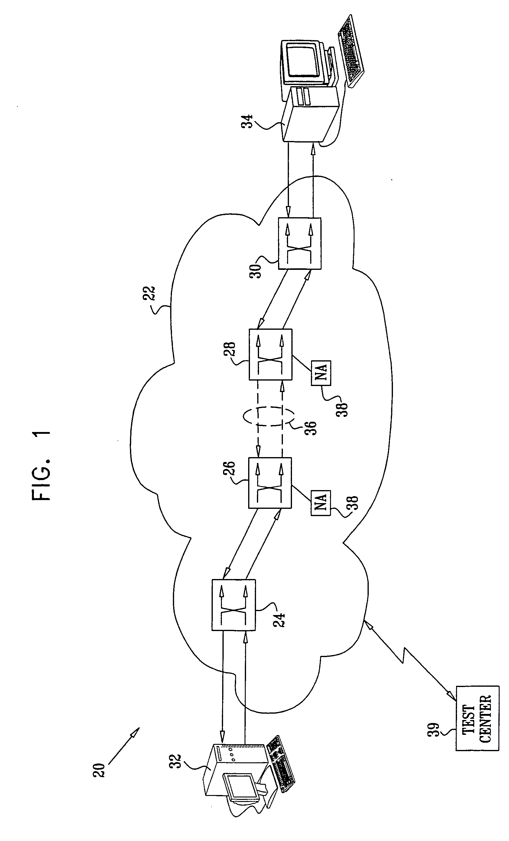
[0043]FIG. 1 is a block diagram that schematically illustrates a distributed testing system 20, which is used to perform diagnostic testing on a network 22, in accordance with an embodiment of the present invention. Network 22 may comprise substantially any sort of network known in the art that is capable of duplex transmission of data packets, such as a local- or wide-area network (LAN or WAN). In the embodiments described hereinbelow, network 22 is assumed to operate in accordance with Ethernet standards, as outlined in the Background of the Invention. Alternatively, the principles of the present invention may similarly be applied in testing networks of other types that allow links to be configured for full- or half-duplex operation.

[0044] In the present example, network 22 comprises switching hardware, represented schematically in FIG. 1 as switches 24, 26, 28 and 30. Typically, the switches comprises LAN hubs or Internet Protocol (IP) routers with Ethernet interface ports, as a...


PUM


Abstract

A method for testing a communication network includes transmitting at least one unidirectional flow over a path through the network, and measuring arrival characteristics of the least one unidirectional flow at a receiving end of the path. The arrival characteristics include at least one of a packet throughput characteristic, a packet delay characteristic, a packet loss characteristic, a packet jitter characteristic and a packet misordering characteristic. A bidirectional flow is transmitted over the path from both ends of the path simultaneously, and the arrival characteristics of the bidirectional flow are measured at least at one of the ends. The arrival characteristics of the unidirectional and bidirectional flows are compared in order to detect a fault in the path.

Description

CROSS-REFERENCE TO RELATED APPLICATION [0001] This application is related to U.S. patent application Ser. No. 09 / 557,256, filed Apr. 24, 2000, which is assigned to the assignee of the present patent application and whose disclosure is incorporated herein by reference.FIELD OF THE INVENTION [0002] The present invention relates generally to digital communication networks, and specifically to testing and discovery of configuration faults in communication networks. BACKGROUND OF THE INVENTION [0003] Ethernet standards now support a large range of different line speeds, from 10 to 1000 MHz, with the option of operating in either full duplex or half duplex mode. IEEE Standards 802.3 and 802.3ab define an auto-negotiation process by which a pair of Ethernet nodes at opposite ends of a link may advertise and negotiate the link speed and duplex mode (full or half) to be used on the link. A useful overview of the auto-negotiation process is provided by Hernandez in “Gigabit Ethernet Auto-Nego...

Claims


Application Information

Patent Timeline
Patent Type & Authority Applications(United States)
IPC IPC(8): H04L12/413
CPCH04L12/2697H04L43/50H04L12/413
Inventor CIDON, ISRAELKAZATCKER, ARIESIDI, MOSHE
Owner CISCO TECH INC
Why Eureka
Try Eureka