Connector which can be reduced in size

a connector and size technology, applied in the direction of coupling device connection, coupling device two-part connection, engagement/disengagement of coupling parts, etc., can solve the problems of friction between the lever and other elements, the thickness of the heart cam is inevitably increased, and it is difficult to reduce the total thickness of the heart cam, so as to reduce the thickness of the cam mechanism

Active Publication Date: 2006-10-05
JAPAN AVIATION ELECTRONICS IND LTD
View PDF6 Cites 6 Cited by
  • Summary
  • Abstract
  • Description
  • Claims
  • Application Information

AI Technical Summary

Benefits of technology

[0008] It is therefore an object of this invention to provide a ca

Problems solved by technology

As a consequence, the heart cam is inevitably increased in thickness in correspondence to the steps.
Therefore, it is difficult to reduce the total thickness of a cam mechanism compr

Method used


Image

  • Connector which can be reduced in size
  • Connector which can be reduced in size
  • Connector which can be reduced in size

Examples


Embodiment Construction

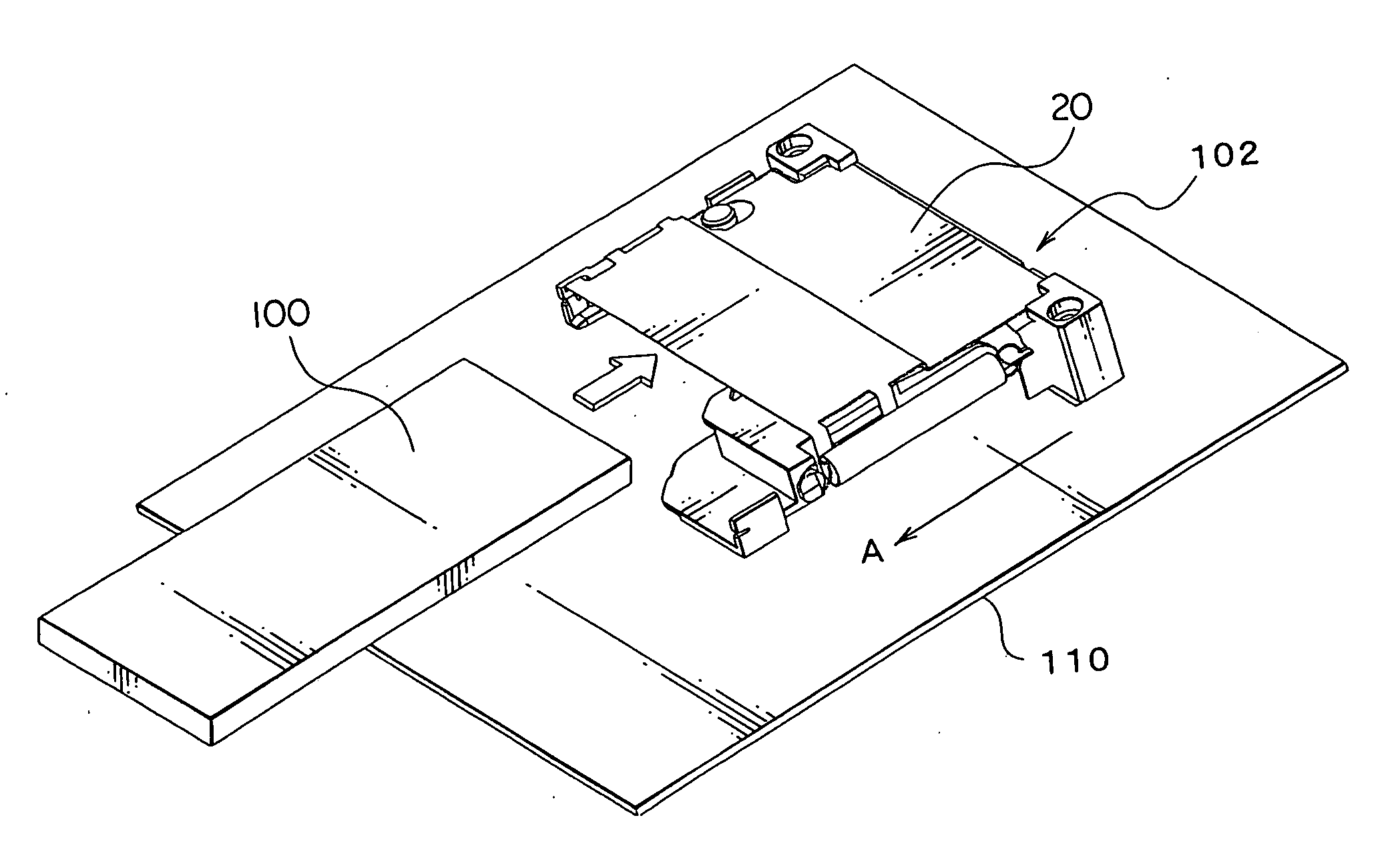
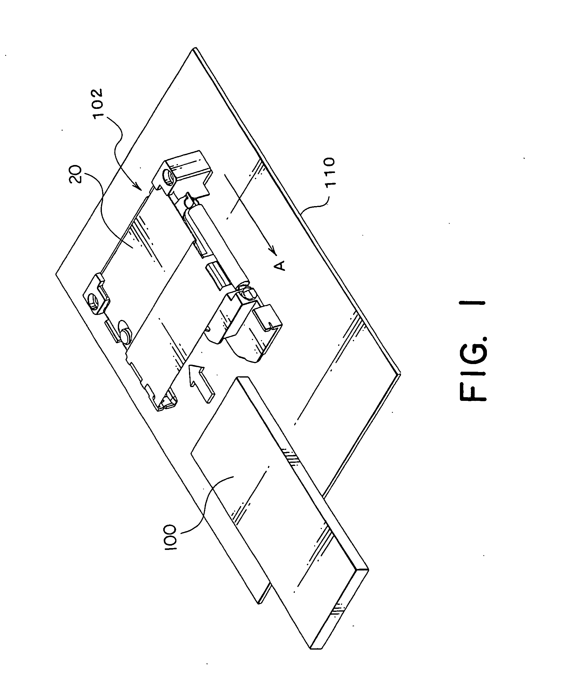
[0036] Referring to FIGS. 1 to 5, description will be made of a structure of a card connector according to an embodiment of this invention.

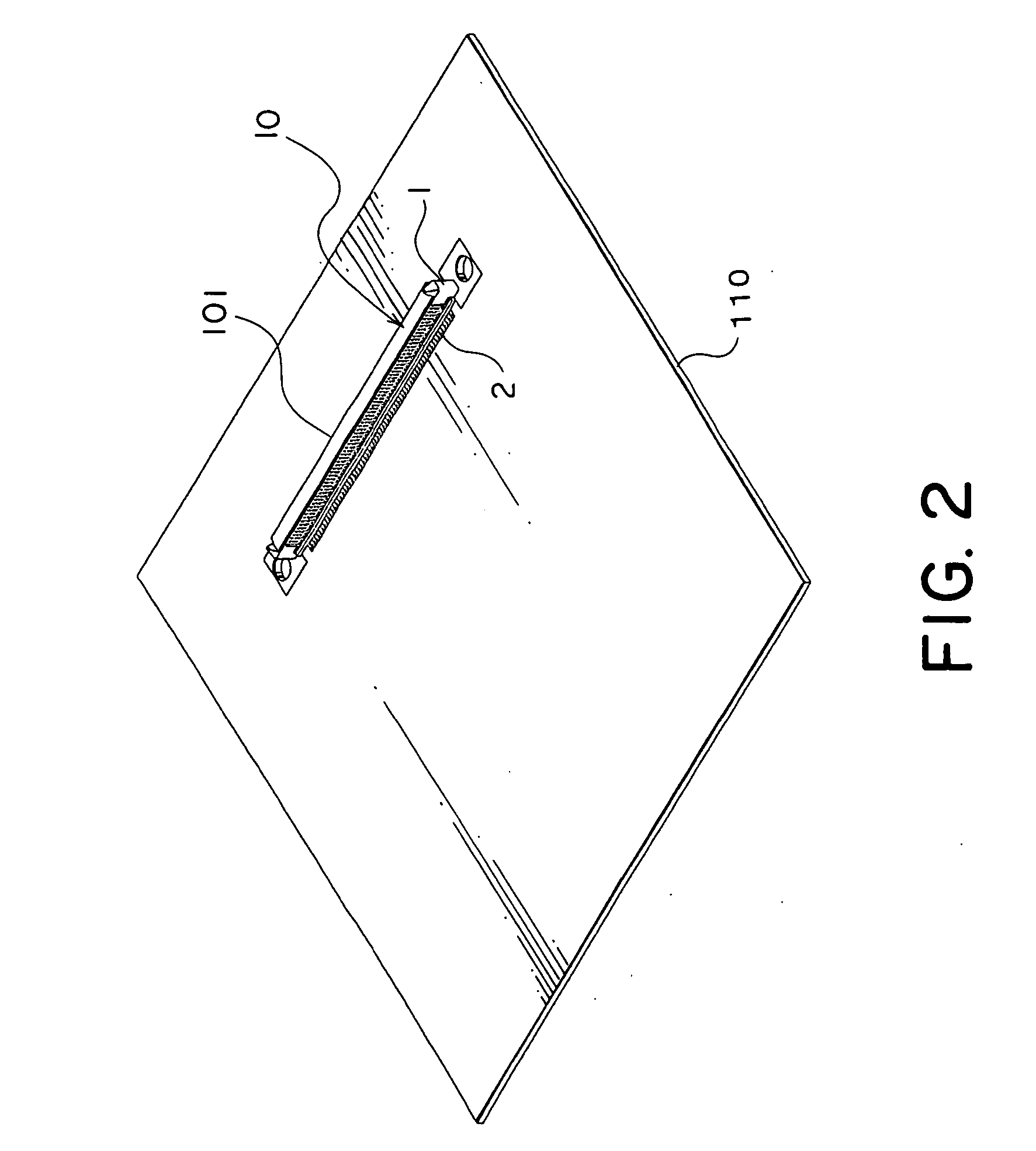
[0037] The card connector illustrated in the figures is depicted by a reference numeral 102. The card connector 102 is mounted on a substrate 110 built in an electronic apparatus and is used for connecting a memory card 100. The card connector 102 comprises a base portion 101 automatically mounted at a predetermined position on the substrate 110, and a frame portion 20 coupled to the base portion 101 and fixed to the substrate 110. The base portion 101 comprises a number of base contacts 2 made of metal and soldered to the substrate 110, and a base housing 1 made of resin and fixedly holding the base contacts 2 by press-fitting.

[0038] The frame portion 20 covers the base portion 101 mounted to the substrate 110 and comprises a locator 3 made of resin, a plurality of contacts 5 made of metal, a housing 30 made of resin, a cover 40 made of metal,...


PUM


Abstract

In a card connector to be connected to a card, An ejecting member is provided so as to be movable along a predetermined plane for ejecting the card in an ejecting direction. The ejecting member has a card contacting portion to be contacted with the card and a cam-operated portion. The ejecting member is urged towards the ejecting direction by a urging member. A cam mechanism is provided so as to movable along the predetermined plane in a direction intersecting the ejecting direction. The cam mechanism is elastically supported by a supporting member so that it is disposed at a predetermined position. The cam mechanism has a cam portion for controlling a position of the ejecting member in cooperation with the cam-operated portion.

Description

[0001] This application claims priority to prior Japanese patent application JP 2005-101847, the disclosure of which is incorporated herein by reference. BACKGROUND OF THE INVENTION [0002] This invention relates to a card connector for use in connecting a card. [0003] At present, various types of cards generally called an IC card or a memory card are used in an electronic apparatus. Typically, the card is removably inserted into a card connector mounted or connected to the electronic apparatus. [0004] For example, a card connector of the type is disclosed in Japanese Unexamined Patent Application Publication (JP-A) No. 2001-267013. The card connector is adapted to be mounted to an electronic apparatus and comprises an insulator of a generally rectangular shape, a plurality of contacts held by the insulator, an eject lever coupled to the insulator to be slidable in inserting and removing directions for ejecting a card, and a spring for continuously urging the eject lever in an ejecti...

Claims


Application Information

Patent Timeline
IPC IPC(8): H01R13/62
CPCH01R13/633H01R12/71H01R12/51H01R13/635
Inventor WADA, TAKAMITSUNAKAMURA, KEISUKEKIMURA, AKIRA
Owner JAPAN AVIATION ELECTRONICS IND LTD
Why Eureka
Try Eureka