Massage device utilizing an unanchored magnet for primary force generation

Inactive Publication Date: 2006-10-05
SOUNDSTARTS
View PDF6 Cites 12 Cited by
  • Summary
  • Abstract
  • Description
  • Claims
  • Application Information

AI Technical Summary

Problems solved by technology

An unbalanced weight on a rotating portion of the motor, or on an apparatus driven by the motor, generates centripetal force in a constantly-changing direction, which translates to reciprocating movement of the motor or apparatus.

Method used


Image

  • Massage device utilizing an unanchored magnet for primary force generation
  • Massage device utilizing an unanchored magnet for primary force generation
  • Massage device utilizing an unanchored magnet for primary force generation

Examples


Embodiment Construction

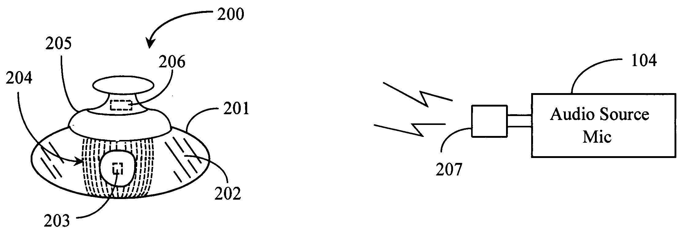
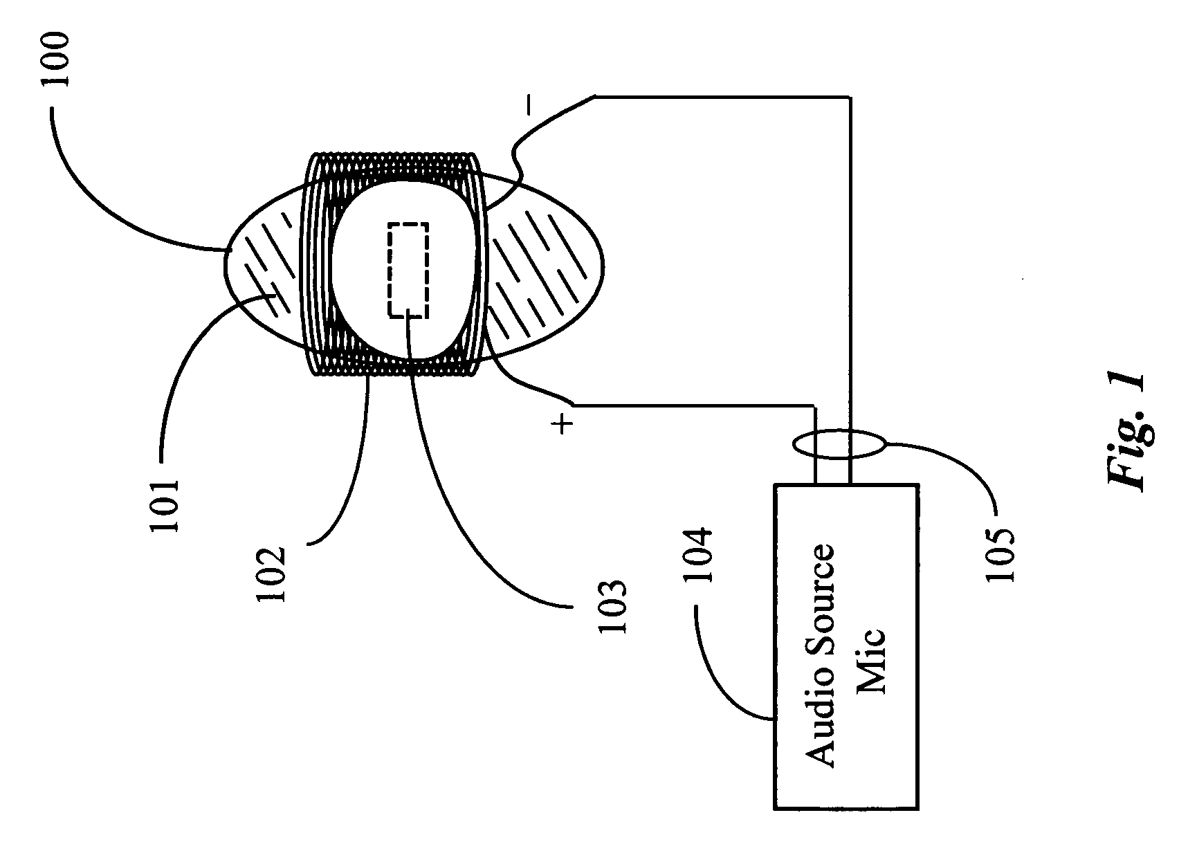
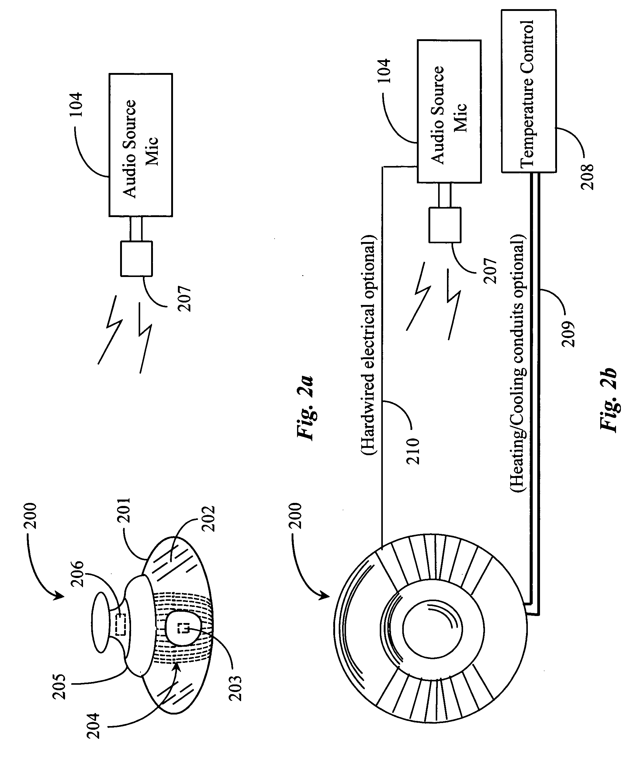
[0026]FIG. 1 is a mostly schematic illustration showing generally how reciprocating motion may be produced in an embodiment of the present invention for a massage or topical treatment device. In this example a closed-container 100, in this case having a roughly egg shape, is at least partially filled with a ferro-magnetic fluid 101. Preferably the fluid completely fills the internal volume of the container, although in some cases partial filling may be used to dampen some effects to be described below. Such ferro-magnetic fluids may be prepared in the art by mixing a finely-ground ferro-magnetic material, like iron, for example, in a liquid or semi-liquid vehicle, such as viscous oil. A permanent magnet 103 is enclosed in the container with the ferro-magnetic fluid 101, and will typically maintain a supported position by nature of the static magnetic field around the permanent magnet and its interaction with the ferro-magnetic fluid. The nature of the suspension and positioning of t...


PUM


Abstract

A therapeutic system for massage comprises a massage device having an activation cell comprising a hollow pocket at least partially filled with a ferro-magnetic fluid, a permanent magnet suspended in the ferro-magnetic fluid, a coil of electrically-conductive material in proximity to the pocket, and a connection interface to connect the coil to a source of varying voltage and current, and a power source of varying voltage for connecting to the connection interface to drive the activation cell.

Description

CROSS-REFERENCE TO RELATED APPLICATIONS [0001] The instant application claims priority to provisional patent application Ser. No. 60 / 666,328, filed Mar. 29, 2005.BACKGROUND OF THE INVENTION [0002] 1. Field of the Invention [0003] The present invention is in the area of devices for assistance in performing massage and other topical procedures on living bodies, and pertains more particularly to the way force and vibration is generated in such devices, and the integration of audio with such generation in addition to magnetic wave therapy. [0004] 2. Discussion of the State of the Art [0005] Massage devices of many sorts and designs are well-known in the art, and conventional massage devices use an offset weighting of a shaft or armature with an electric motor to generate oscillating forces, which causes reciprocal translation of at least a portion of the device. An unbalanced weight on a rotating portion of the motor, or on an apparatus driven by the motor, generates centripetal force i...

Claims


Application Information

Patent Timeline
Patent Type & Authority Applications(United States)
IPC IPC(8): A61H1/00
CPCA61H7/001A61H23/02A61H23/0236A61H23/04A61H2201/0207A61H2201/0214A61N2/06A61H2201/0242A61H2201/0257A61H2201/0285A61H2201/1645A61H2201/5048A61N2/002A61H2201/0228
Inventor BOYS, MARK A.
Owner SOUNDSTARTS
Why Eureka
Try Eureka