Trajectory prediction

Inactive Publication Date: 2006-10-05
THE BOEING CO
View PDF33 Cites 61 Cited by
  • Summary
  • Abstract
  • Description
  • Claims
  • Application Information

AI Technical Summary

Benefits of technology

[0009] The present invention is directed to methods and systems for improved prediction of the movement of vehicles through an airspace. In one embodiment, a method for predicting movement of a vehicle in an airspace from a first location to a second location includes predicting movement based upon at least one modulated data signal configured to communicate a plurality of sensor-perceived first locations of the vehicle, including time correlating

Problems solved by technology

Unfortunately, use of typical radars, especially transponder radars, may not generate location data that is accurate enough to reduce separations to a minimum possible according to vehicle performance capabilities.
Latency of voice contact is sometimes better but more often worse than that of radar, including concerns that the correct vehicle is being addressed (e.g. “Flight 440 turn left”).
In addit

Method used


Image

  • Trajectory prediction
  • Trajectory prediction
  • Trajectory prediction

Examples


Embodiment Construction

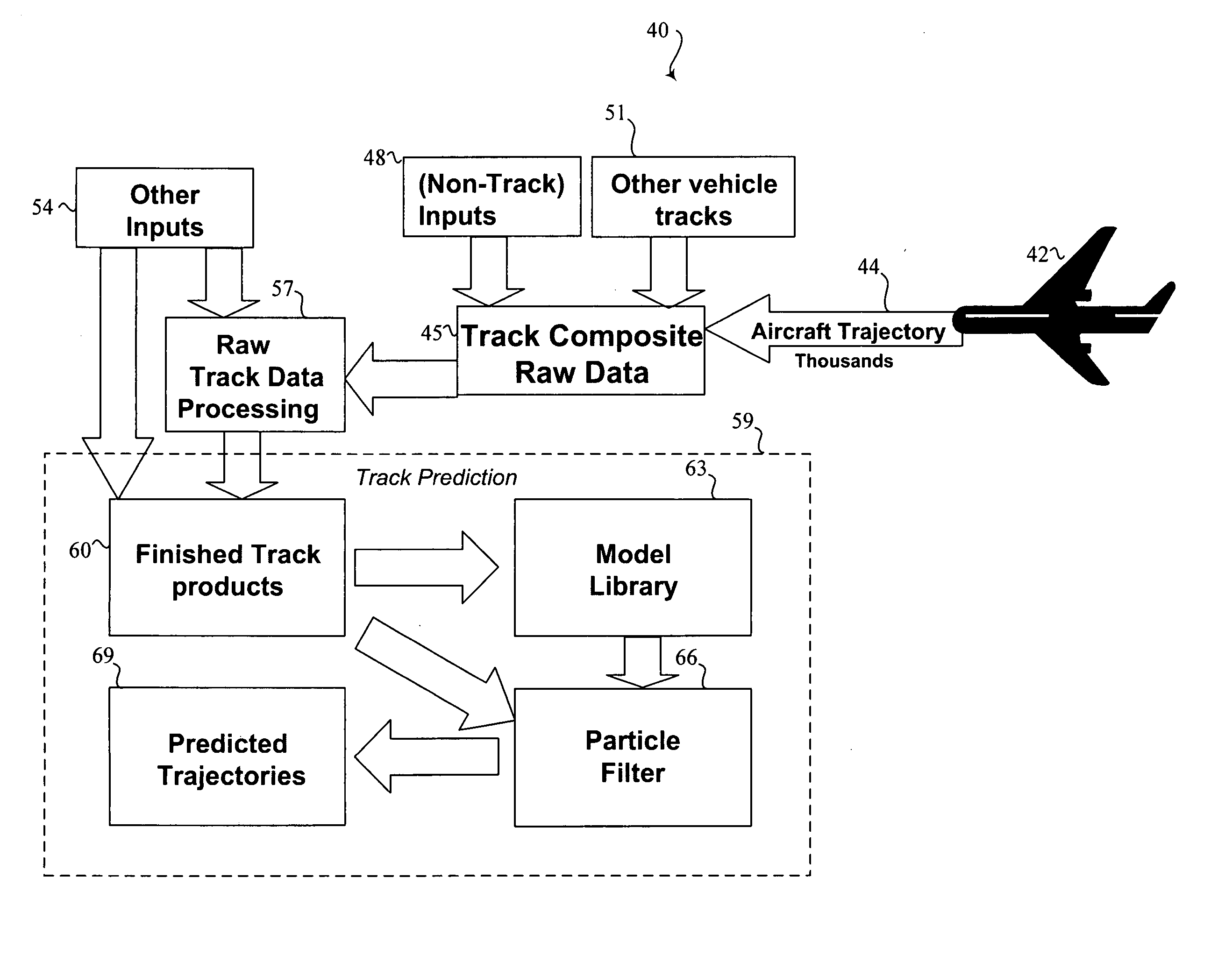
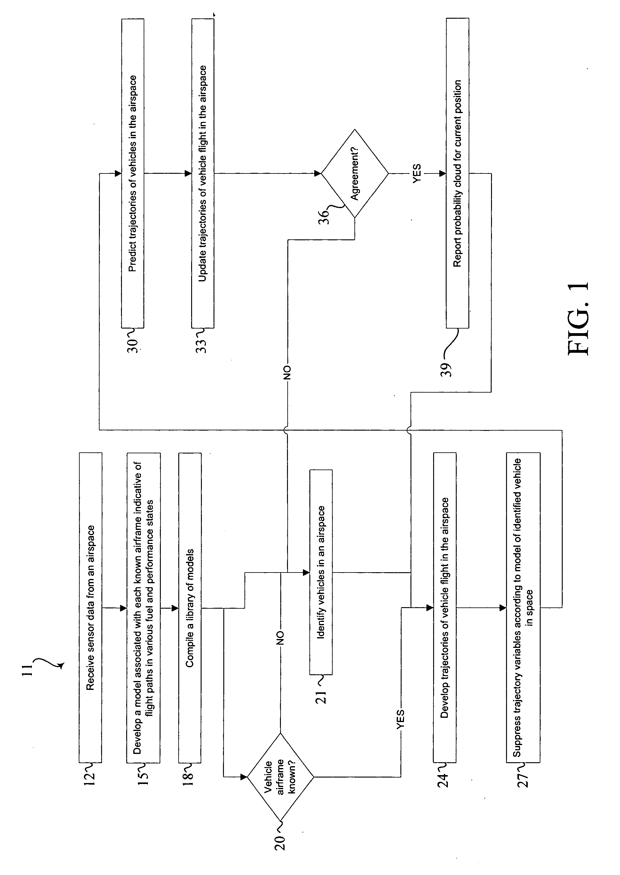
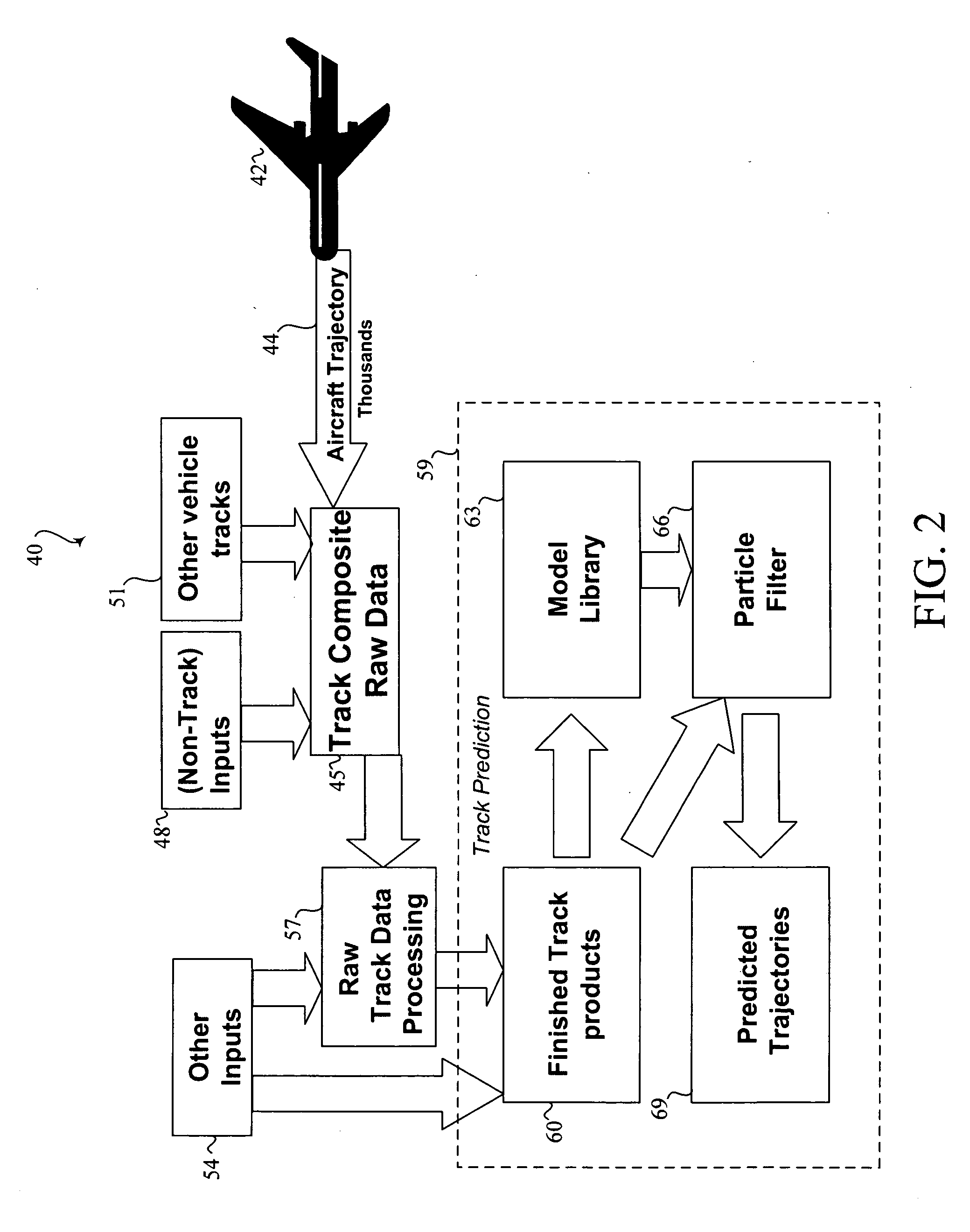
[0014] The present invention relates to generating and thus predicting trajectories of vehicles in an airspace. Many specific details of certain embodiments of the invention are set forth in the following description and in FIGS. 1, 2, and 3 to provide a thorough understanding of such embodiments. One skilled in the art, however, will understand that the present invention may have additional embodiments, or that the present invention may be practiced without several of the details described in the following description.

[0015] By way of overview, the problem of tracking a vehicle through an airspace includes processing noisy measurements received from one or more sensors over time to form tracks about potential targets. Sensors are typically very “ego-centric” in that measurements are in spherical coordinates (azimuth, elevation and range, or more likely without elevation) from returns received from the sensor over the current period. Radar return reception, in particular, is noisy ...


PUM


Abstract

Methods and systems for improved prediction of the movement of vehicles through an airspace are disclosed. In one embodiment, a method for predicting movement of a vehicle in an airspace from a first location to a second location, the predicting based upon at least one data signal configured to communicate a plurality of sensor-perceived first locations of the vehicle includes time correlating the plurality of sensor perceived first locations. The plurality of sensor-perceived first locations are particle filtered to generate a plurality of confidences each corresponding with one of a plurality of predicted locations, each confidence representing a likelihood that the corresponding predicted location includes the second location.

Description

FIELD OF THE INVENTION [0001] This invention relates generally to air traffic control and, more specifically, to vehicle tracking. BACKGROUND OF THE INVENTION [0002] Military and civilian control of any designated airspace relies upon accurate projection of a vehicle's movement through the space. Existing means for tracking vehicles on displays use a continuous line showing movement, but typically do not show where a vehicle is now, only where that vehicle has been in the past. [0003] Where the vehicles are controlled through the space, a maximum number of vehicles in the space is limited by a separation radius necessary to anticipate movement needs of the several vehicles, whether that radius be determined as a function of distance with respect to each other or to hazards within the space (e.g. weather, terrain, obstructions, etc.). A magnitude of separation radius is driven by the performance characteristics of the vehicle. For instance, a looming mountain presents a much smaller ...

Claims


Application Information

Patent Timeline
IPC IPC(8): G01C21/00G01S19/48
CPCG01S5/0027G01S13/723G01S13/86G08G5/0052
Inventor WILSON, ROBERTWHITLEY, TEDESTKOWSKI, REGINA
Owner THE BOEING CO
Why Eureka
Try Eureka