Sample analyzing method and sample analyzing device

Active Publication Date: 2006-10-05
ARKRAY INC
View PDF4 Cites 31 Cited by
  • Summary
  • Abstract
  • Description
  • Claims
  • Application Information

AI Technical Summary

Benefits of technology

[0006] An object of the present invention is to make possible to detect whether or not a target amo

Problems solved by technology

Further, this causes non-uniformity in the concentration of glucose or reductant (oxidant) in the reaction field.
As a result, the response current for analysis does not nece

Method used


Image

  • Sample analyzing method and sample analyzing device
  • Sample analyzing method and sample analyzing device
  • Sample analyzing method and sample analyzing device

Examples


Embodiment Construction

[0032] Hereinafter, the best mode for embodying the present invention will be described specifically, with reference to the drawings.

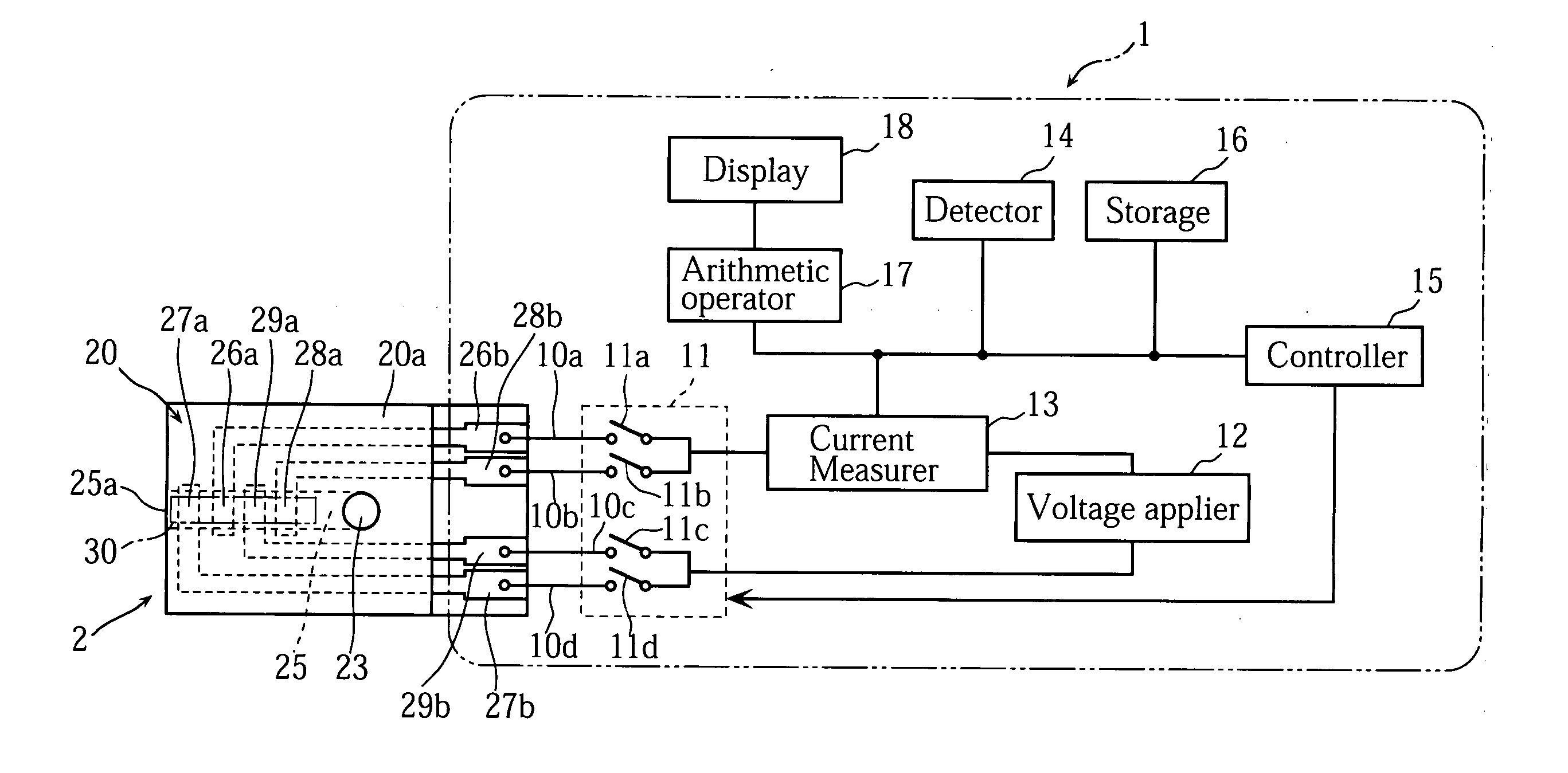
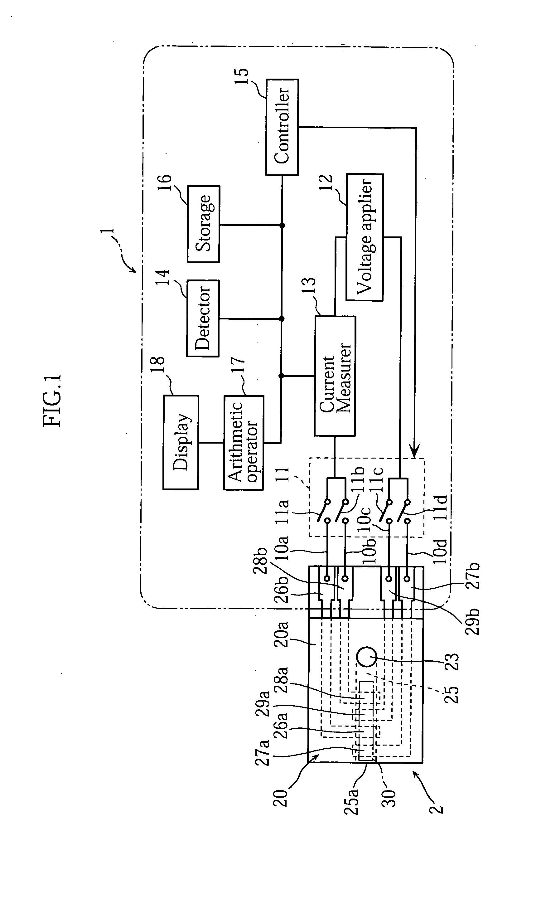
[0033]FIG. 1 shows a sample analyzer 1 which measures a specific component in a sample, using a biosensor 2 attached thereto.

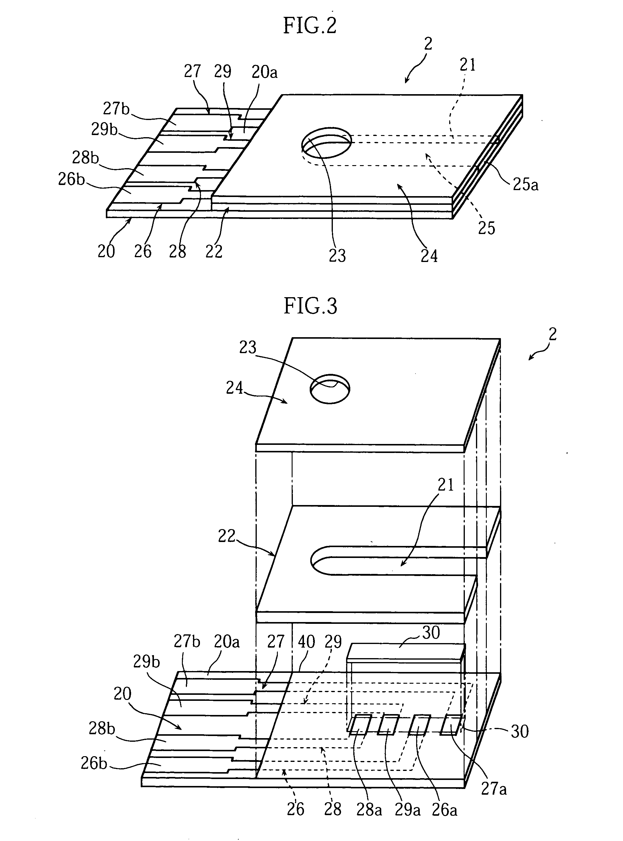
[0034] As clearly shown in FIG. 2 and FIG. 3, the biosensor 2 includes a substrate 20 which has a first surface 20a laminated with a spacer 22 and a cover 24. The spacer 22 has a narrow slit 21. The cover 24 has a hole 23. With the spacer 22 and the cover 24 laminated on the first surface 20a of the substrate 20, the substrate 20, the spacer 22 and the cover 24 provide a capillary 25. The capillary 25 communicates with outside, via a sample inlet 25a and the hole 23. In other words, the biosensor 2 is able to supply a sample via the sample inlet 25a to the capillary 25, and the sample supplied from the sample inlet 25a is able to move by capillarity toward the hole 23 in the capillary 25.

[0035] The first surface 20a of the sub...


PUM


Abstract

This invention relates to a technique for analyzing a sample. A sample analyzer (1) provided by the invention includes: a voltage applier (12) for applying a voltage to a reaction field which includes a sample; a response measurer (13) for measurement of a response to the voltage applied to the reaction field; a selector (11) for selecting a first voltage application state for measurement of a first response for use in calculation necessary for analyzing the sample or a second voltage application state for measurement of a second response for use in determining whether or not the reaction field has been supplied with a target amount of the sample; an arithmetic operator (17) for calculation necessary for analyzing the sample based on the first response; a determiner (17) for determination, based on the second response, on whether or not the reaction field has been supplied with the target amount of sample; and a controller (15) which makes the selector select the second voltage application state after making the selector select the first voltage application state.

Description

TECHNICAL FIELD [0001] The present invention relates to a technique for analyzing samples. BACKGROUND ART [0002] As a common method for analyzing samples, an oxidation-reduction reaction is used. An example is a quantitative procedure disclosed in JP-A2001-330581, which makes use of a biosensor that provides a liquid reaction field. [0003] As will be expected from FIG. 6 of the present application, the biosensor disclosed in the gazette makes use of a capillary which is formed by laminating a cover 92 onto a substrate 90 via a spacer 91, for measurement of blood sugar level. The substrate 90 has a surface formed with a working electrode W, a counter electrode C and a liquid junction sensing electrode S. Though not illustrated in the figure, a reagent region is provided so as to bridge at least an end of the working electrode W with an end of the counter electrode C. The reagent region includes an oxidation-reduction enzyme and an electron transfer material. [0004] In this biosensor ...

Claims


Application Information

Patent Timeline
IPC IPC(8): G06G7/00G01N27/416G01N33/487
CPCG01N27/3274
Inventor SATO, YOSHIHARUKATSUKI, KOJI
Owner ARKRAY INC
Why Eureka
Try Eureka