Portable solar panel with attachment points

a solar panel and solar energy technology, applied in the direction of generator/motor, light radiation electric generator, greenhouse gas reduction, etc., can solve the problems of uneven solar energy distribution, high production cost and low efficiency, and high cost of photovoltaics, so as to improve the efficiency of solar panels

Inactive Publication Date: 2006-10-12
LOCHER STEVE
View PDF16 Cites 177 Cited by
  • Summary
  • Abstract
  • Description
  • Claims
  • Application Information

AI Technical Summary

Benefits of technology

[0010] The present invention further discloses a battery multi-interface unit to interface with the portable solar panel, which is an electronic device which has one or more battery interface capabilities, AC/DC current conversions and outlets, and input connectors for the purpose of charging batteries, transferring power from one battery to another, and operating electric devices with AC/DC currents. In addition, interfaces for electric current input from solar, wind, generator, vehicle, or other energy sources may be provided for recharging any voltage ...

Problems solved by technology

However, photovoltaics are very expensive, in terms of high production cost and low efficiency.
The major drawback of this configuration is the uneven distribution of solar energy: during daylight operation, the photovoltaic array can produce excess power while during night time or periods of reduced sun li...

Method used


Image

  • Portable solar panel with attachment points
  • Portable solar panel with attachment points
  • Portable solar panel with attachment points

Examples


Embodiment Construction

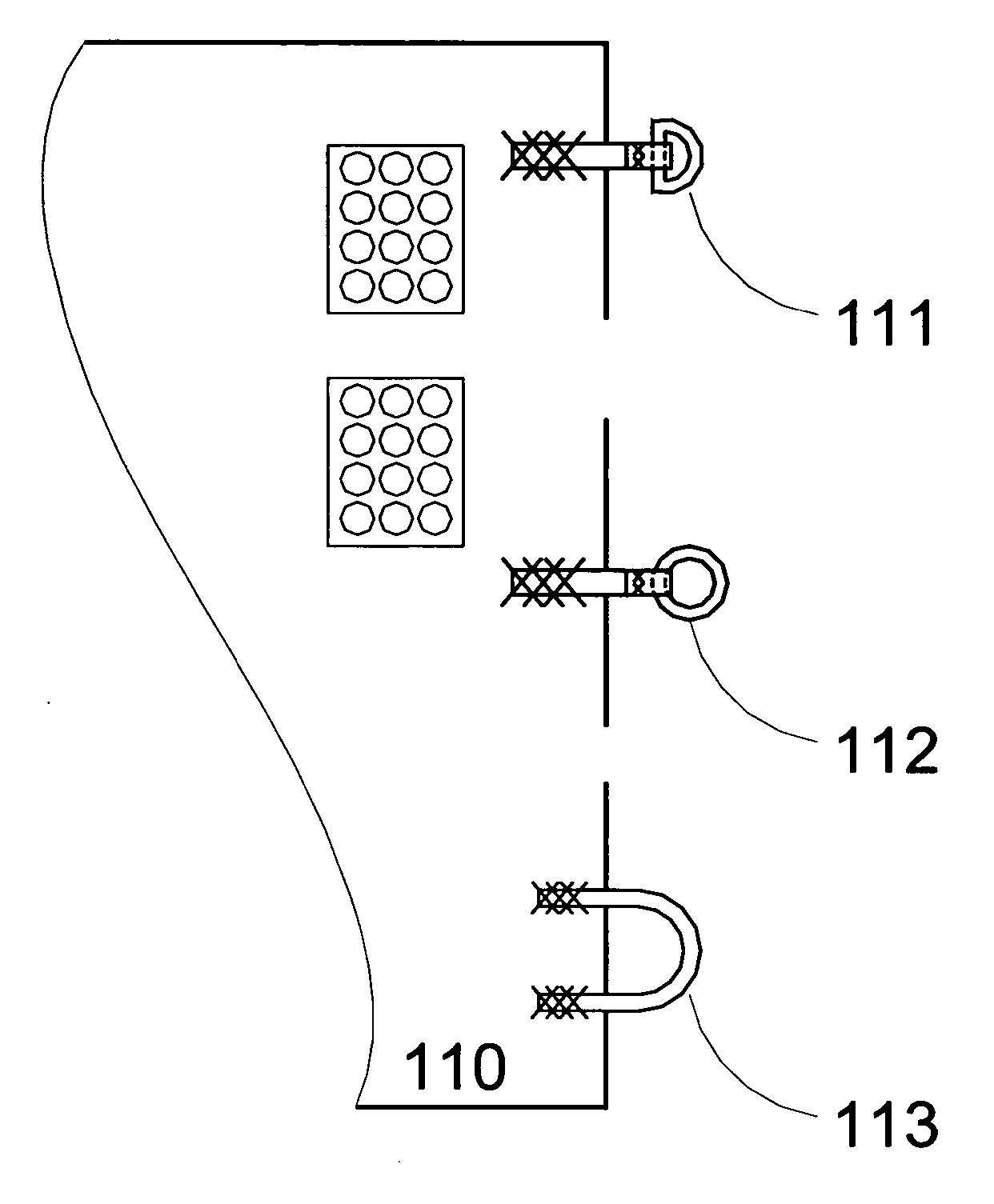
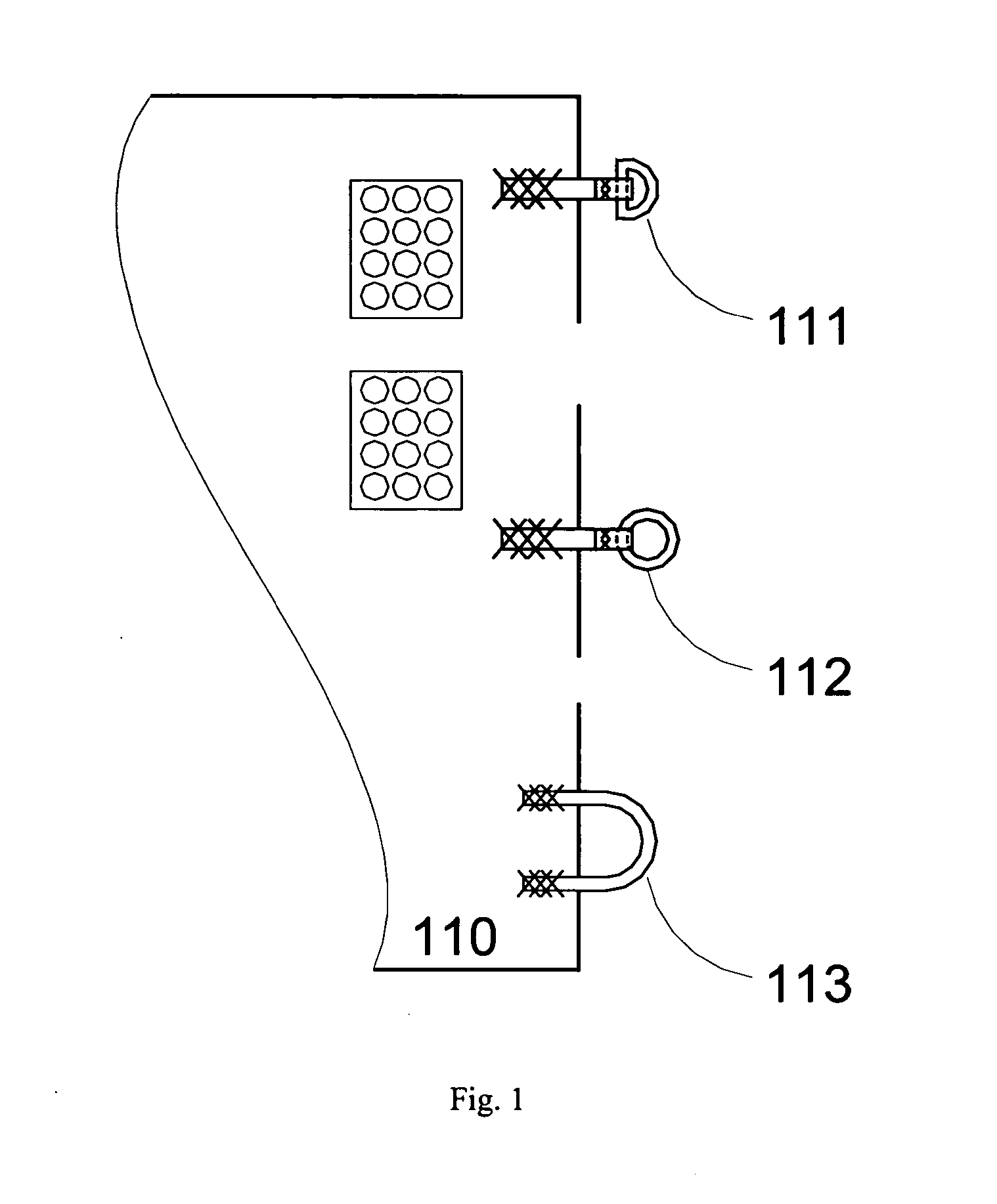
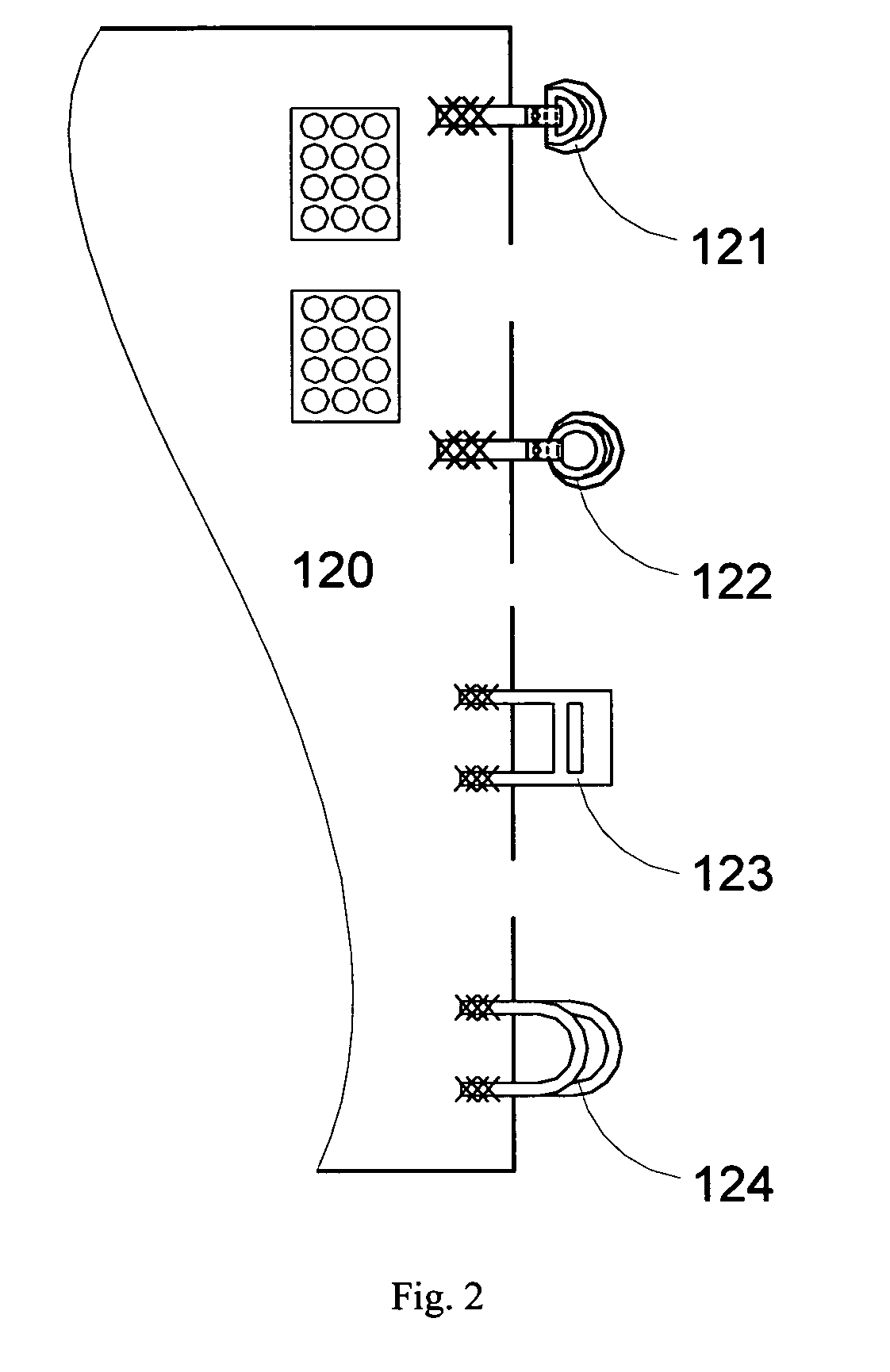
[0029] The present invention discloses a method and an apparatus for a universal mounting strapping system, with a preferred application to solar panel systems such as a portable solar panel or a field portable battery charger utilizing a solar panel such as a solar tarp. The disclosed portable solar panel system comprises an efficiency solar panel or array with a plurality of attachment points, together with a versatile, adjustable strapping system, capable of attaching to nearly any object, such as back packs, luggage, vehicles, boats, permanent and portable shelters and buildings, mechanical equipment, and also natural objects such as trees, and rocks.

[0030] The solar panel according to the present invention can be rigid or flexible with different attachment units designed for rigid or flexible connections. When the solar panel is to be used, the strap assembly allows the panel to be secured to a support structure. The flexible solar panel has various advantages, for example, it...


PUM


Abstract

The present invention discloses a portable solar tarp or a field portable battery charger employing a solar tarp, utilizing flexible solar panels, solar fabric, or solar film. Around the perimeter of the solar tarp is a series of attachment points for straps. The attachment points can be grommets, loops, buckles, hooks, buttons, or grab loops and lines, and to which connected various straps (webbing, line, cord, or cable). The present invention further discloses a versatile, adjustable strapping system utilizing straps, buckles, and hooks. The present invention strapping system can attach almost any object to nearly any other object, such as back packs, luggage, vehicles, boats, permanent and portable shelters and buildings, mechanical equipment, and natural objects such as trees, rocks. The solar panel according to the present invention can have the photovoltaic cells wired individually, or in a single line, because when parts of the photovoltaic system is subjected to shade, or if due to space constraint, parts of the photovoltaic system is covered or folded away, the remaining photovoltaic cells with useable energy are still able to function at peak capacity, since the covered cells will not become an energy drain upon the remaining cells. Further, the photovoltaic system is able to harness all available energy, regardless of the required or desired voltage and/or amperage for the system, thus converting any and all available energy into a useable current to either recharge batteries, or power a load.

Description

[0001] This application claims priority from U.S. provisional applications Ser. No. 60 / 669,230 filed Apr. 7, 2005, entitled “Photovoltaic cells and modules wiring”; Ser. No. 60 / 669,229 filed Apr. 7, 2005, entitled “Strapping system for photovoltaic cells”; Ser. No. 60 / 669,228 filed Apr. 7, 2005, entitled “Backpack strapping system for photovoltaic cells”; Ser. No. 60 / 669,227 filed Apr. 7, 2005, entitled “Vehicle strapping system for photovoltaic cells”; Ser. No. 60 / 669,226 filed Apr. 7, 2005, entitled “Tent strapping system for photovoltaic cells”; Ser. No. 60 / 669,150 filed Apr. 7, 2005, entitled “Field portable solar battery charger with backpack and vehicle strapping system”; and Ser. No. 60 / 681,658 filed May 16, 2005, entitled “Battery Multi-Interface Unit”; which are incorporated herein by reference.FIELD OF THE INVENTION [0002] The present invention relates generally to portable solar panels and, more particularly, to a method and apparatus of a portable solar panel or a field ...

Claims


Application Information

Patent Timeline
IPC IPC(8): H02N6/00
CPCB60R16/03H01L31/02H01L31/042H02S40/38Y02B10/10Y02E10/50H02S30/20H02J7/355H02J7/35H02J2310/46Y02E10/56Y02E70/30H02S10/40
Inventor LOCHER, STEVE
Owner LOCHER STEVE
Why Eureka
Try Eureka