
Compressed air powered vehicle

Inactive Publication Date: 2006-10-12
COLE WILLIAM JAY
View PDF14 Cites 69 Cited by
  • Summary
  • Abstract
  • Description
  • Claims
  • Application Information

AI Technical Summary

Problems solved by technology

This is due both to the decreasing oil supply worldwide and the increasing levels of pollution which internal combustion engines cause.

Method used


Image

  • Compressed air powered vehicle
  • Compressed air powered vehicle
  • Compressed air powered vehicle

Examples


Embodiment Construction

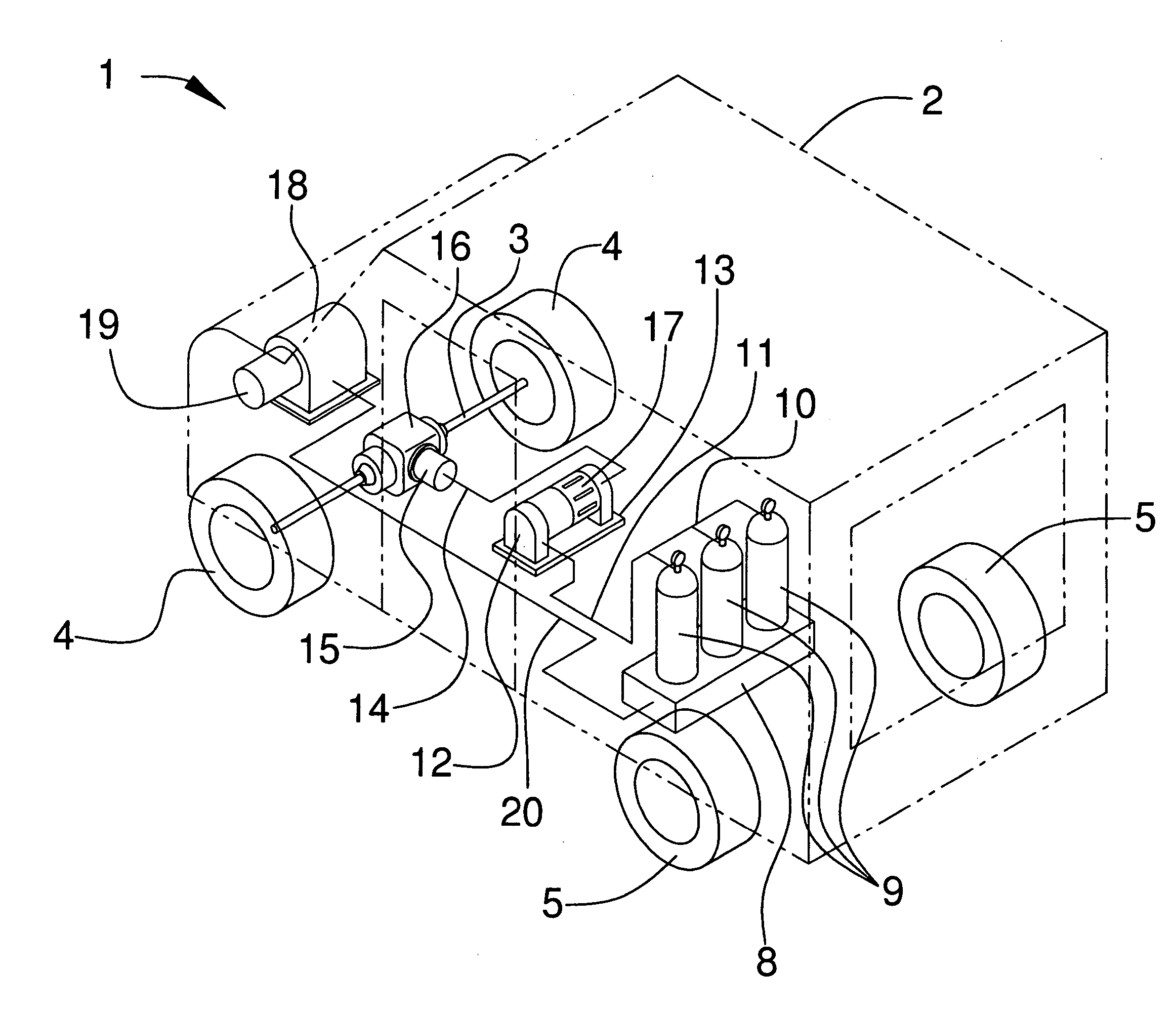
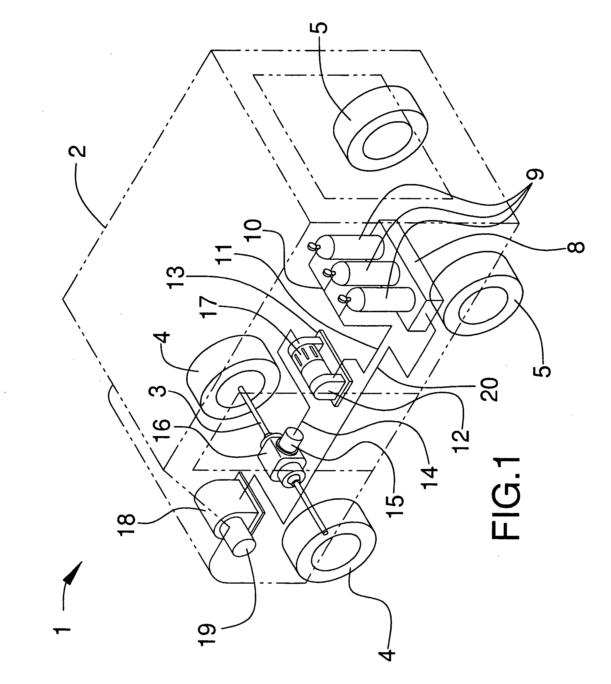
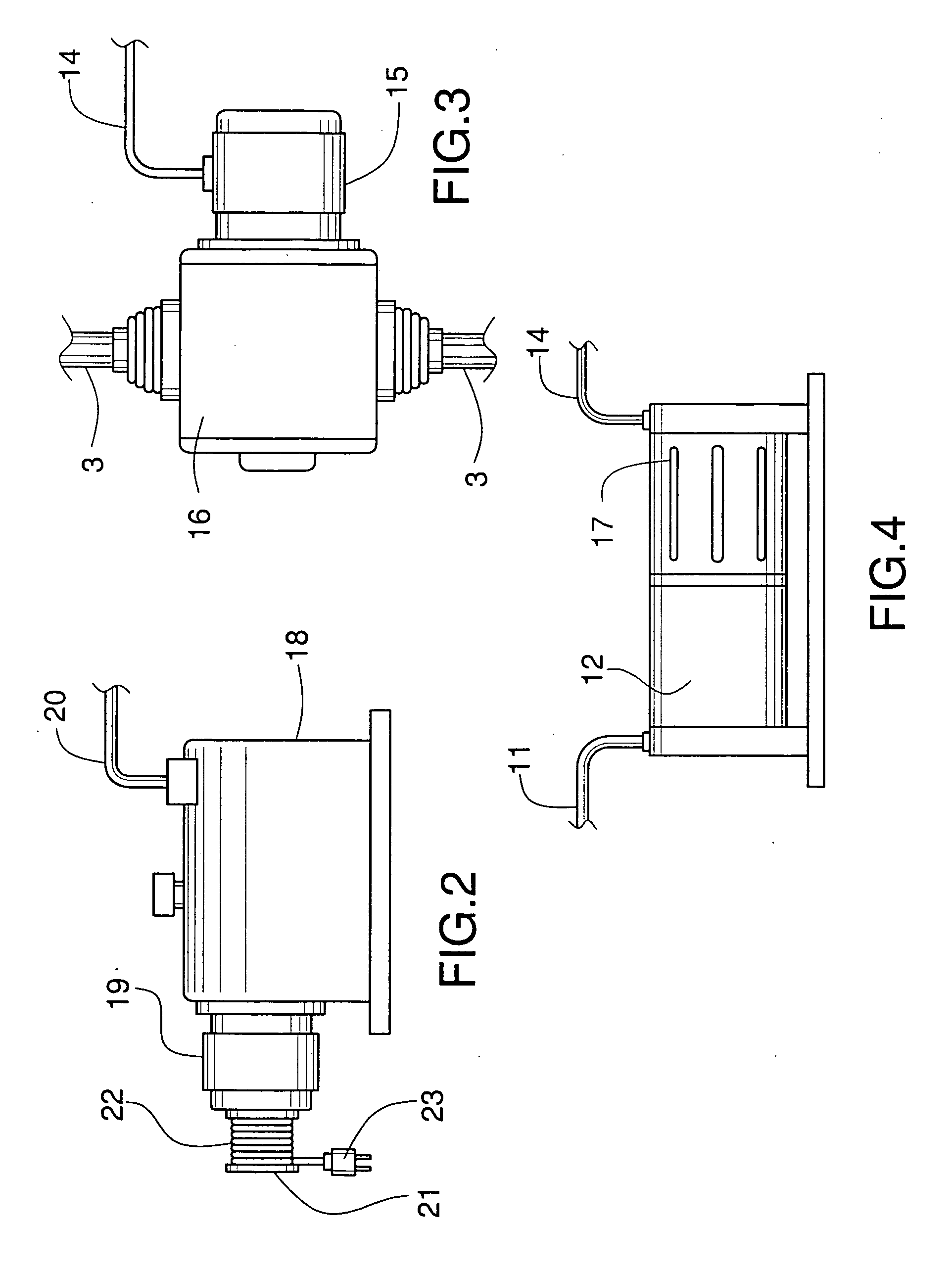
[0012] Referring initially to FIGS. 1-5, an illustrative embodiment of the compressed air powered vehicle, hereinafter vehicle, of the present invention is generally indicated by reference numeral 1. The vehicle 1 includes a vehicle frame (not shown) which supports a vehicle chassis 2. When used herein, “chassis” shall be construed to mean either the vehicle chassis 2 or vehicle frame. The vehicle chassis 2 may be the size and configuration of a delivery-type vehicle, such as a mail delivery vehicle, for example, as shown. Alternatively, the chassis 2 may have any desired shape which is consistent with the use requirements of the vehicle 1. The vehicle 1 further includes a front axle 3 which is provided at the front end of the vehicle frame and on which is mounted a pair of front wheels 4. A rear axle (not shown) is provided at the rear end of the vehicle frame, and a pair of rear wheels 5 is provided on the rear axle.

[0013] A tank base 8 is provided in the vehicle chassis 2, typic...


PUM


Abstract

A compressed air powered vehicle is disclosed. The vehicle includes a vehicle chassis having wheels. An electric drive motor drivingly engages at least one of the wheels. An electric generator is electrically connected to the electric drive motor, and an air motor drivingly engaging the electric generator. A compressed air source is pneumatically connected to the air motor, and an air compressor is provided on the chassis and pneumatically connected to the compressed air source to replenish compressed air in the compressed air tanks as needed.

Description

FIELD OF THE INVENTION [0001] The present invention relates to automobiles powered by electricity generated by compressed air. More particularly, the present invention relates to a compressed air powered vehicle which is environmentally-friendly and fuel efficient. BACKGROUND OF THE INVENTION [0002] In recent years, considerable research effort has been made to develop alternative sources of fuel for automobiles. This is due both to the decreasing oil supply worldwide and the increasing levels of pollution which internal combustion engines cause. Much of the research has focused on the use of electricity as an alternative to gasoline as a fuel for automobiles. Unlike gasoline, electricity can be generated as needed for use and also does not emit pollutant byproducts which are harmful to the environment. [0003] Therefore, an electric vehicle is needed which includes an on-board electrical generator to generate electricity for powering of the vehicle. SUMMARY OF THE INVENTION [0004] T...

Claims


Application Information

Patent Timeline
IPC IPC(8): B60K3/00
CPCB60K1/00B60Y2400/15B60K7/0007B60K6/00
Inventor COLE, WILLIAM JAY
Owner COLE WILLIAM JAY
Learn More