Ducted fan vertical take-off and landing vehicle

a vertical take-off and landing and ducted fan technology, applied in vehicles, vertical landing/take-off aircraft, rotorcraft, etc., can solve the problems of difficult and too cumbersome steering of flying vehicles without, and the non-practical commodity of personal flying vehicles in our society

Inactive Publication Date: 2006-10-12
WALTON JOH PAUL CHRISTOPHER
View PDF10 Cites 288 Cited by
  • Summary
  • Abstract
  • Description
  • Claims
  • Application Information

AI Technical Summary

Benefits of technology

[0010] This invention is intended to be used as a manned or unmanned flight vehicle. It is designed for use by milit

Problems solved by technology

With present day VTOL aircraft and hovercrafts there is not a practical way to make a personal flying vehicle.
The problem is that once in motion inertia takes over and it is difficult and too cumbersome to steer a flying ve

Method used


Image

  • Ducted fan vertical take-off and landing vehicle
  • Ducted fan vertical take-off and landing vehicle
  • Ducted fan vertical take-off and landing vehicle

Examples


Embodiment Construction

—FIGS. 1A, 1D, 2B, 4A, 4B, 4C, 4D, 5A, 5B, 5C, 5D, 6A, 6C, 8, 9A, 9B, 9C, 9D—PREFERRED EMBODIMENT

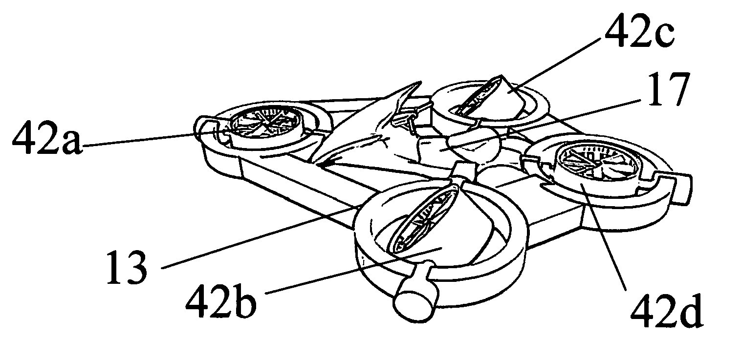
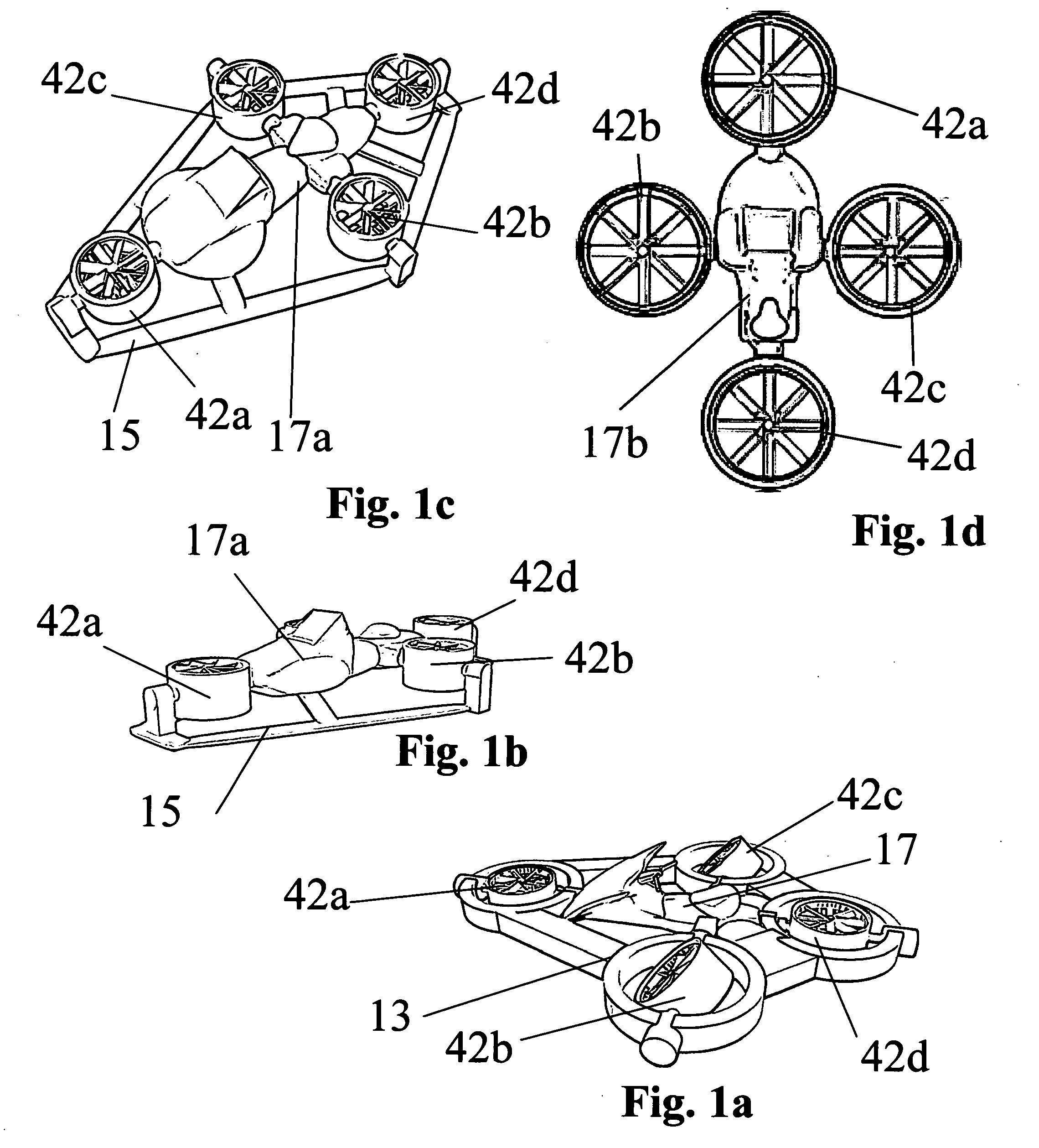
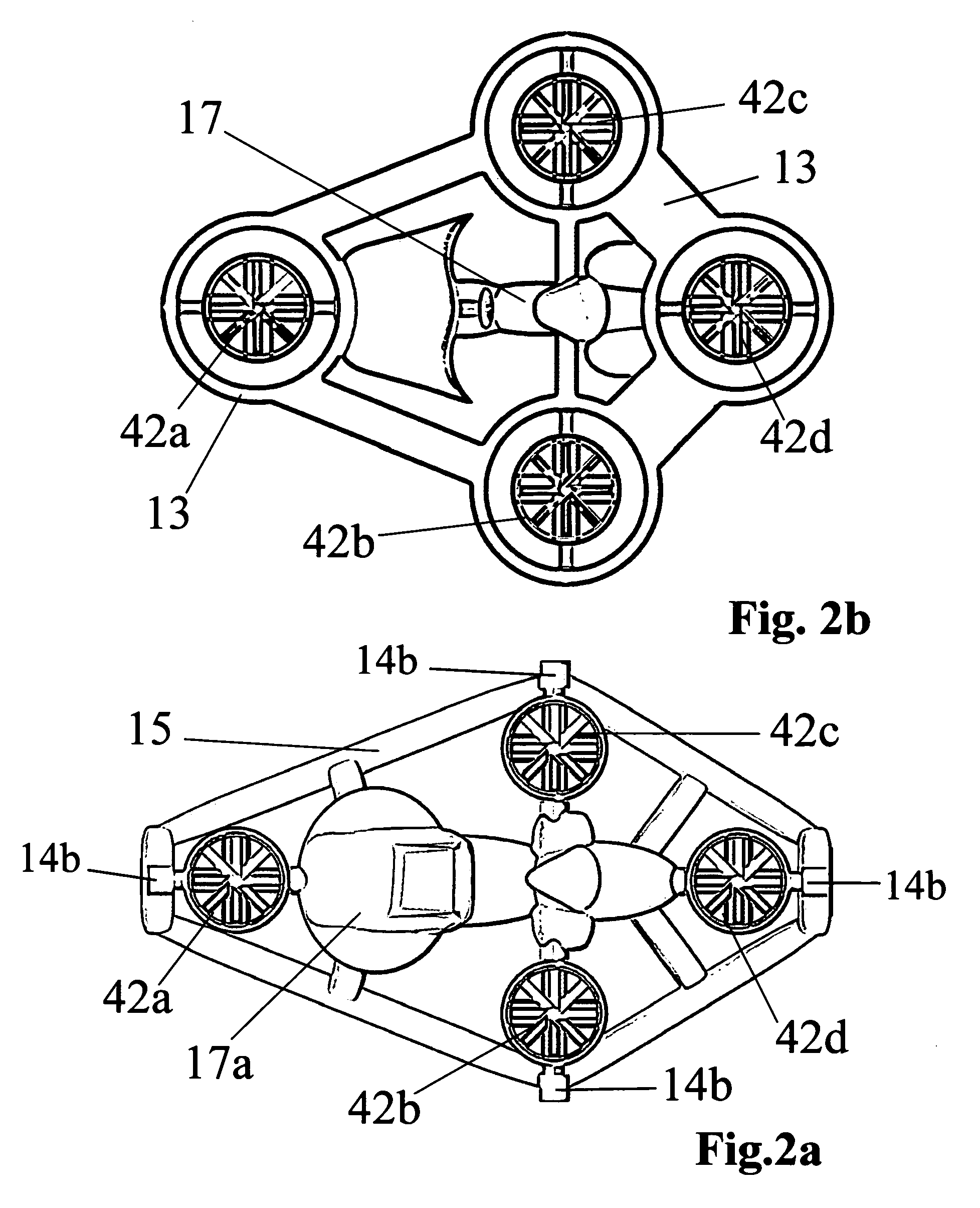
[0074] The preferred embodiments of the present invention will now be described with reference to FIGS. 1A, 1D, 2B, 4A, 4B, 4C, 4D, 5A, 5B, 5C, 5D, 6A, 6C, 8, 9A, 9B, 9C, and 9D of the drawings. Some identical elements in the various figures are identified with the same reference numerals. Some identical elements have been given different reference numerals to identify their position and to avoid confusion.

[0075] The first preferred embodiment is described in reference to FIGS. 1d, 5a, 5b, 5c, 6c, 8, 9a, 9b, 9c, and 9d of the invention, a vertical take-off and landing vehicle (VTOL). Shown in FIG. 1d (top view) of a vertical take-off and landing vehicle containing a fuselage 17b and a set of four identical ducted fan units set to the front 42a, left 42b, right 42c, and rear 42d of the fuselage 17b. Each ducted fan unit is powered by its own power source (shown in FIG. 8, top view withou...


PUM


Abstract

A vertical take-off and landing vehicle comprised of a fuselage having a front, a rear, and two lateral sides and a set of four thrusters set to the front, the left, the right, and the rear of said fuselage. The thrusters are either independently powered thrusters or could utilize a single power source. The thrusters, which are ducted fan units capable of providing a vertically upward force to the aircraft, are provided with such redundancy that the aircraft can hover with up to two thrusters inoperative. The thrusters are comprised of a set of two counter rotating propellers both of which creates lift. The two counter rotating propellers cancel out the torque effect normally created by using only one propeller. The Ducted fan units being movable between a first position in which they provide vertical lift and a second position in which they provide horizontal thrust using a set of servos and gears.

Description

CROSS-REFERENCE TO RELATED APPLICATIONS: [0001] This application claims the benefit of provisional patent application Ser. No. 60 / 628822, file. 2004 Nov. 17 by the present inventor.FEDERALLY SPONSORED RESEARCH [0002] Not Applicable SEQUENCE LISTING OR PROGRAM [0003] Not Applicable BACKGROUND OF THE INVENTION [0004] 1. Field of Invention [0005] This invention generally relates to a vertical take-off and landing (VTOL) vehicle comprising a fuselage having a front, rear, and two sides, and four externally mounted thrusters. The four thrusters, which are ducted fan units, are positioned around the outside of the fuselage and located to the front, right, left, and rear of the fuselage. The four ducted fan units are capable of providing a vertically upward force to the aircraft, and provide such redundancy that the aircraft can hover with up to two thrusters inoperative on each side of the fuselage. Each thruster, on each side of the fuselage, creates lift from the propellers as well as f...

Claims


Application Information

Patent Timeline
IPC IPC(8): B64C27/08
CPCB64C29/0033B64C27/20B64U50/20B64U50/14B64U10/14B64U10/20
Inventor WALTON, JOH-PAUL CHRISTOPHER
Owner WALTON JOH PAUL CHRISTOPHER
Why Eureka
Try Eureka