Method and system for enhanced radiation detection

a radiation detection and radiation detection technology, applied in the field of radiation detection systems, can solve the problems of limiting the spatial resolution of the imaging system, increasing the complexity of the system, and imposing constraints on the minimum size of the detector, so as to improve the detection of specific objects

Inactive Publication Date: 2006-10-12
THERMOPHOTONICS
View PDF7 Cites 2 Cited by
  • Summary
  • Abstract
  • Description
  • Claims
  • Application Information

AI Technical Summary

Benefits of technology

[0012] In one exemplary embodiment of a sensor, a focal plane array comprising a radiation detector with mapping elements formed by a substrate with thermal detection material disposed upon it. In this embodiment, the radiation detector is segmented into an array of mapping elements by voids in the substrate and the corresponding thermal detection material. The voids can be formed by removing portions of the substrate and detection material to create “perforations” between adjacent detectors to minimize thermal conduction between detectors within the array. The voids can also be formed by removing portions of the detection material and leaving the underlying substrate substantially unchanged. Alternatively, the voids can be formed using deposition or lithographic techniques so that detection material is disposed or deposited on the substrate only in areas of interest, thereby forming the array of mapping elements, also referred to herein as detectors. The voids between adjacent detectors serves to minimizes thermal conduction between detectors within the array.
[0018] In another exemplary embodiment, a radiation detection sensor includes mapping elements formed with a substrate, and protruding from the top surface of the substrate is an array of columns. The sensor includes radiation detectors having a radiation sensitive layer, such as a radiation sensitive film, and a thermal conversion material, such as an absorber, that may be disposed upon a top surface of the individual columns within the array. The columns provide thermal isolation between the radiation detectors and the substrate. Spatial separation of columns within the array provide thermal and radiant isolation between the radiation detectors upon the tops of individual columns. An array of radiation detectors allows detection, or identification, of the radiation emitted from an object.
[0023] The columns of the radiation detection sensor can be various shapes and sizes. For example, in one embodiment the columns are cylinders. In another embodiment a top surface of the column is larger than the base of the column thereby maximizing the amount of incoming radiation that impinges upon an individual detector. The columns can have any desired cross section, for example, circular, oval, square, rectangular, or any other multi-sided polygon shape desired. In addition, there may be multiple detectors supported by a single column or multiple columns may support a single detector. For example, a detector may have a spherical shape and there may be three columns supporting the detector. Other configurations of detectors and support structures may also be used.
[0028] In another exemplary embodiment of a radiation detection system a target illumination source illuminates, or “paints” an object. Radiation reflected from the object may then be collected by collection optics and focused onto the focal plane array. The target illumination source may be tunable. For example, the target illumination source may include optics or controls to shape the spectrum of the radiation output by the target illumination source. In another example, the target illumination source may include multiple sources, each of which outputs a desired spectrum of radiation. The output of the target illumination source may be mixed, or combined, in any desired combination so that a desired output spectrum is achieved. In this manner the object may be painted with radiation of a desired spectral content which may improve the detection of specific objects.

Problems solved by technology

The size and active area of each sensor in the array limits the spatial resolution of the imaging system.
Likewise, the need to make electrical connection to the individual detectors, for example to measure a resistance change, can increase system complexity as well as impose constraints on the minimum size for the detectors.
However, liquid crystal films suffer from poor resolution because the thermal energy “bleeds” across the film or coating.

Method used


Image

  • Method and system for enhanced radiation detection
  • Method and system for enhanced radiation detection
  • Method and system for enhanced radiation detection

Examples


Embodiment Construction

[0068] The word “exemplary” is used herein to mean “serving as an example, instance, or illustration.” Embodiment described herein are “exemplary” and are not necessarily to be construed as preferred or advantageous over other embodiments.

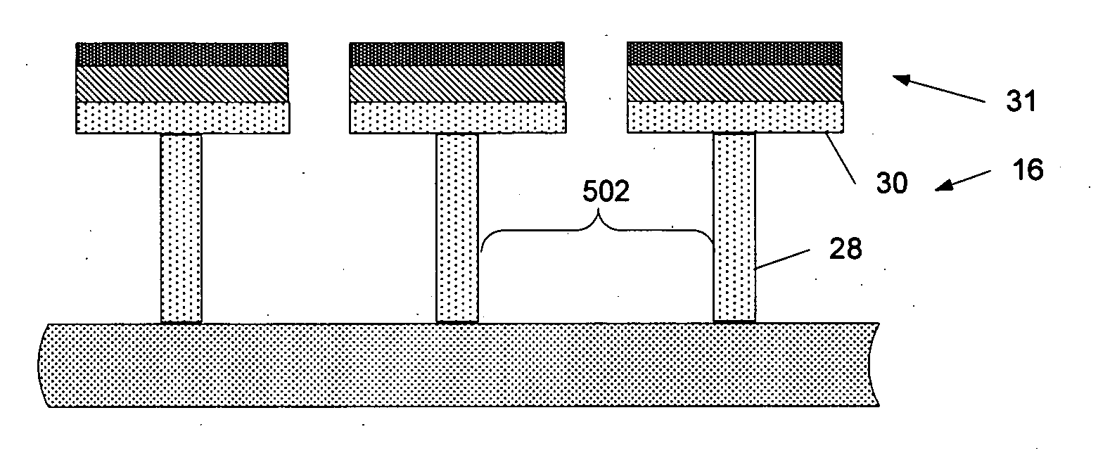
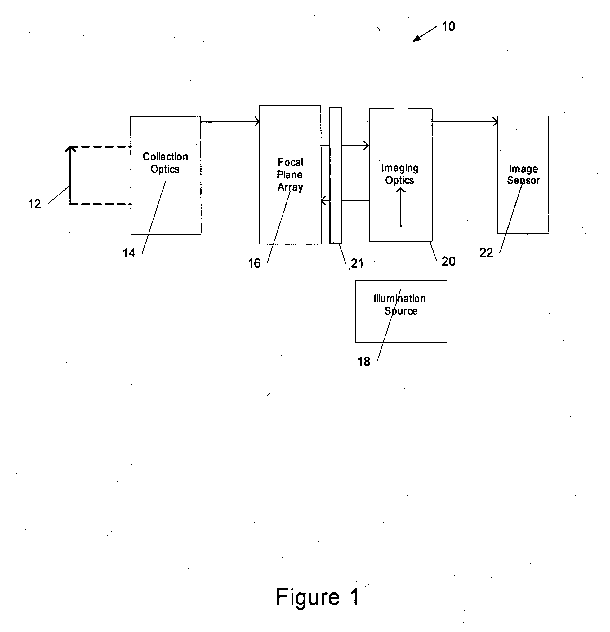
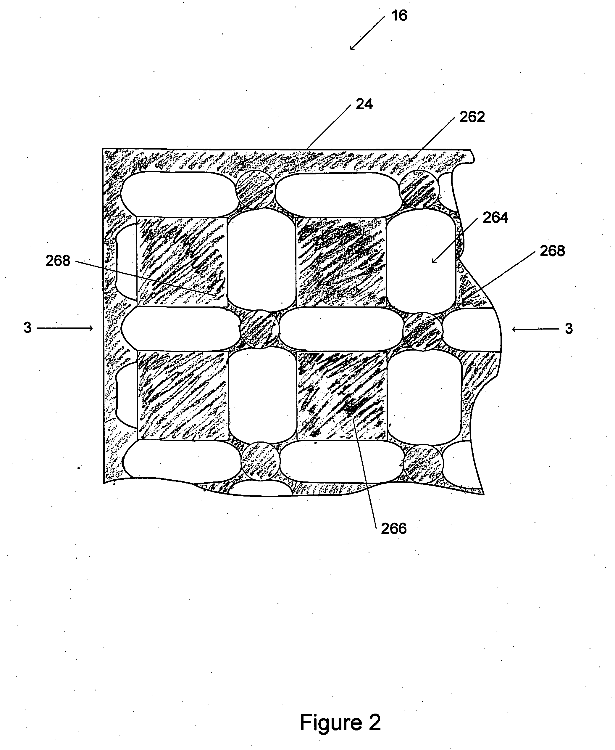
[0069] In accordance with the invention, a radiation detection sensor includes a radiation detector that is segmented into an array of mapping elements, also referred to herein as detectors. The mapping elements are substantially thermally isolated from each other and comprise pixels of a visual thermal energy map. The radiation detector receives thermal energy and generates the visual thermal energy map, which is provided by the sensor for viewing. The mapping elements of the radiation detector may be minimally connected to adjacent mapping elements, or the mapping elements may be substantially physically isolated from each other. The mapping elements may be micro-disposed, such that individual mapping elements are substantially thermally isolate...


PUM


Abstract

A radiation detection sensor includes a radiation detector that is segmented into an array of mapping elements, or detectors. The mapping elements may be micro-disposed, such that individual mapping elements are substantially thermally isolated from each other and comprise pixels of a visual thermal energy map. The mapping elements of the radiation detector may be minimally connected to adjacent radiation detectors, or the mapping elements may be substantially physically isolated from each other.

Description

REFERENCE TO RELATED APPLICATION [0001] This application is a continuation-in-part of U.S. patent application Ser. No. 11 / 005,671 filed Dec. 6, 2004 entitled “Method and System for Enhanced Radiation Detection” by Jorge Roman et al. Priority of the filing date of the prior application is hereby claimed, and the disclosure of the prior application is hereby incorporated by reference.BACKGROUND [0002] 1. Field [0003] The present invention relates generally to radiation detection systems and in particular to enhanced resolution radiation detection. [0004] 2. Description of the Related Art [0005] Detection of radiation that is emitted from objects and is outside of the visible spectrum can provide useful information. For example, detection systems have been developed for sensing infrared radiation (IR) from an object or source in a target space. Infrared imagers, also called thermal imagers, are instruments that create images of heat instead of light, by converting radiated IR energy to...

Claims


Application Information

Patent Timeline
Patent Type & Authority Applications(United States)
IPC IPC(8): G01J5/48
CPCG01J5/06G01J2005/0077G01J5/10G01J5/061
Inventor ROMAN, JORGESCHMIDT, GREGORY W.SCHMIDT, MARY JEANSCHMIDT, WILLIAMFRYER, ROBERTSASMOR, HENRI
Owner THERMOPHOTONICS
Why Eureka
Try Eureka