Thermal Incision Apparatus, System and Method

a technology of incision apparatus and incision head, which is applied in the field of thermal incision apparatus, system and method, can solve the problems of reducing the efficiency of incision, reducing the precision of cutting, etc., and achieves the effects of reducing heat conduction, improving thermal delivery capability, and facilitating sustained operation

Active Publication Date: 2019-04-04
EGGERS & ASSOC LLC
View PDF0 Cites 4 Cited by
  • Summary
  • Abstract
  • Description
  • Claims
  • Application Information

AI Technical Summary

Benefits of technology

[0047]An advantage of the present invention is an improved surgical blade for the thermal cutting of tissue without the need for a surgically sharp cutting edge, and methods of making such blades. Another advantage is a durable blade having improved thermal delivery capabilities over a broad range of conditions encountered in the thermal cutting of tissue. A yet another advantage is a thermally regulated heated blade having a cutting region that is maintained at a nearly uniform temperature over the full range of surgical cutting conditions. A further advantage is a thermal cutting blade that permits sustained operation without adherence of tissue or coagulum during surgical use and without the need for a non-stick coating. A yet further advantage is an electrically heated blade that reduces conduction of heat from the heated portion of the surgical blade to the blade supporting handpiece. Another advantage is an electrically heated surgical blade having thick-film printed electrical leads characterized by a low electrical resistance to reduce Joulean heating within a blade support member by resistive losses in the electrical leads. A further advantage is a surgical instrument for the thermal cutting of tissue whose heated portion of the blade has a heat capacity that is sufficiently low to enable heat up of the blade from room temperature to a thermal cutting temperature within about one second. Another advantage is the elimination the of a costly control system external to the handpiece. A further advantage is a method of manufacturing a surgical blade to maximize temperature uniformity of the heated portion of the blade and minimize thermal conduction from the heating element and tissue cutting regions of the blade to the handpiece supporting the blade. These and other advantages will be apparent to the skilled artisan based on the present disclosure.
is an improved surgical blade for the thermal cutting of tissue without the need for a surgically sharp cutting edge, and methods of making such blades. Another advantage is a durable blade having improved thermal delivery capabilities over a broad range of conditions encountered in the thermal cutting of tissue. A yet another advantage is a thermally regulated heated blade having a cutting region that is maintained at a nearly uniform temperature over the full range of surgical cutting conditions. A further advantage is a thermal cutting blade that permits sustained operation without adherence of tissue or coagulum during surgical use and without the need for a non-stick coating. A yet further advantage is an electrically heated blade that reduces conduction of heat from the heated portion of the surgical blade to the blade supporting handpiece. Another advantage is an electrically heated surgical blade having thick-film printed electrical leads characterized by a low electrical resistance to reduce Joulean heating within a blade support member by resistive losses in the electrical leads. A further advantage is a surgical instrument for the thermal cutting of tissue whose heated portion of the blade has a heat capacity that is sufficiently low to enable heat up of the blade from room temperature to a thermal cutting temperature within about one second. Another advantage is the elimination the of a costly control system external to the handpiece. A further advantage is a method of manufacturing a surgical blade to maximize temperature uniformity of the heated portion of the blade and minimize thermal conduction from the heating element and tissue cutting regions of the blade to the handpiece supporting the blade. These and other advantages will be apparent to the skilled artisan based on the present disclosure.

Problems solved by technology

In particular, bleeding that occurs when tissue is incised obscures the surgeon's vision, delays the operation, and reduces the precision of cutting.
In a cutting mode, the electrical arcing and corresponding current flow results in a highly intense, but localized heating, which causes cell destruction and tissue severance.
Disadvantageously, the application of tamponade by pressing the surgical instrument against the tissue containing the transected vessel(s) to temporarily interrupt the flow of blood from vessels (e.g., vessels having a lumen size greater than about 1 mm) is not possible since such applied pressure would prevent the essential arc formation.
However, the current intensity is generally insufficient to enable the cutting of tissue and no electrical arcs are formed as in the case of the monopolar electrosurgery modality described above.
Bipolar devices, however, generally require other auxiliary means for cutting the tissue being coagulated.
The requisite thinness of the wire resulted in marginal strength or rigidity, thus restricting applications of such instruments to spot coagulation with the application of a minimum level of pressure to the targeted vessel.
This, unfortunately, represents an attempt to stop bleeding after cutting, as opposed to a more desirable procedure for simultaneous cutting with coagulation.
Such non-stick coating unavoidably introduces an additional thermal impedance between the heated cutting blade and the tissue owing to the very low thermal conductivity of available non-stick coating materials.
A disadvantage associated with prior art resistively heated thermal cutting devices that employ a ferromagnetic blade substrate or ferromagnetic coatings on a non-ferromagnetic hairpin-shaped round or flat wire substrate, is concerned with a lack of sufficient localization of heat at the blunt thermal cutting edge.
Such elevated temperatures poses a risk that the support portions of the heating element that are proximal to those portions intended for tissue contact and cutting may contact tissue or organs not selected for incision causing unwanted thermal injury to the tissue or organs.
Another disadvantage associated with prior art resistively heated thermal cutting devices that employ a ferromagnetic blade substrate or a ferromagnetic coating on a non-ferromagnetic substrate is the operating temperature of the blade can extend over a wide range from the minimum allowed temperature for thermal cutting of tissue (viz., 400 to 500 C) to the Curie temperature of the ferromagnetic material, which can be as high as 600 to 700 C. In practice, the skin depth of a ferromagnetic material actually increases only gradually as the ferromagnetic heating element approaches the Curie temperature.
This wide operating temperature range of the ferromagnetic heating element above the minimum required thermal cutting temperature of 500 C produces smoke that obscures visibility and necessitates the use of auxiliary smoke evacuation apparatus and methods, further complicating the surgical procedure.
Another disadvantage associated with prior art ferromagnetic resistively heated devices for thermal cutting of tissue is concerned with the requirement that they must be powered by a specially designed or dedicated radiofrequency power supply operating at frequencies ranging from about 300 kHz to over 20 MHz.
Yet another disadvantage of some prior art ferromagnetic resistively heated devices for thermal cutting of tissue is concerned with their inability to apply tamponade with the heated blade member to [a] interrupt the flow of blood long enough to allow the heated blade to effect the sealing of the transected blood vessels or [b] apply heat to pre-seal larger blood vessels before they are transected.
Of course, such added equipment requirements pose budgetary concerns to health care institutions.

Method used


Image

  • Thermal Incision Apparatus, System and Method
  • Thermal Incision Apparatus, System and Method
  • Thermal Incision Apparatus, System and Method

Examples


example

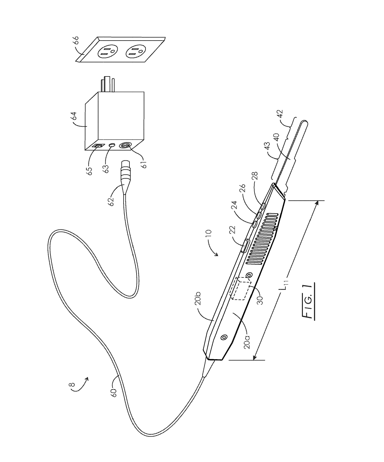
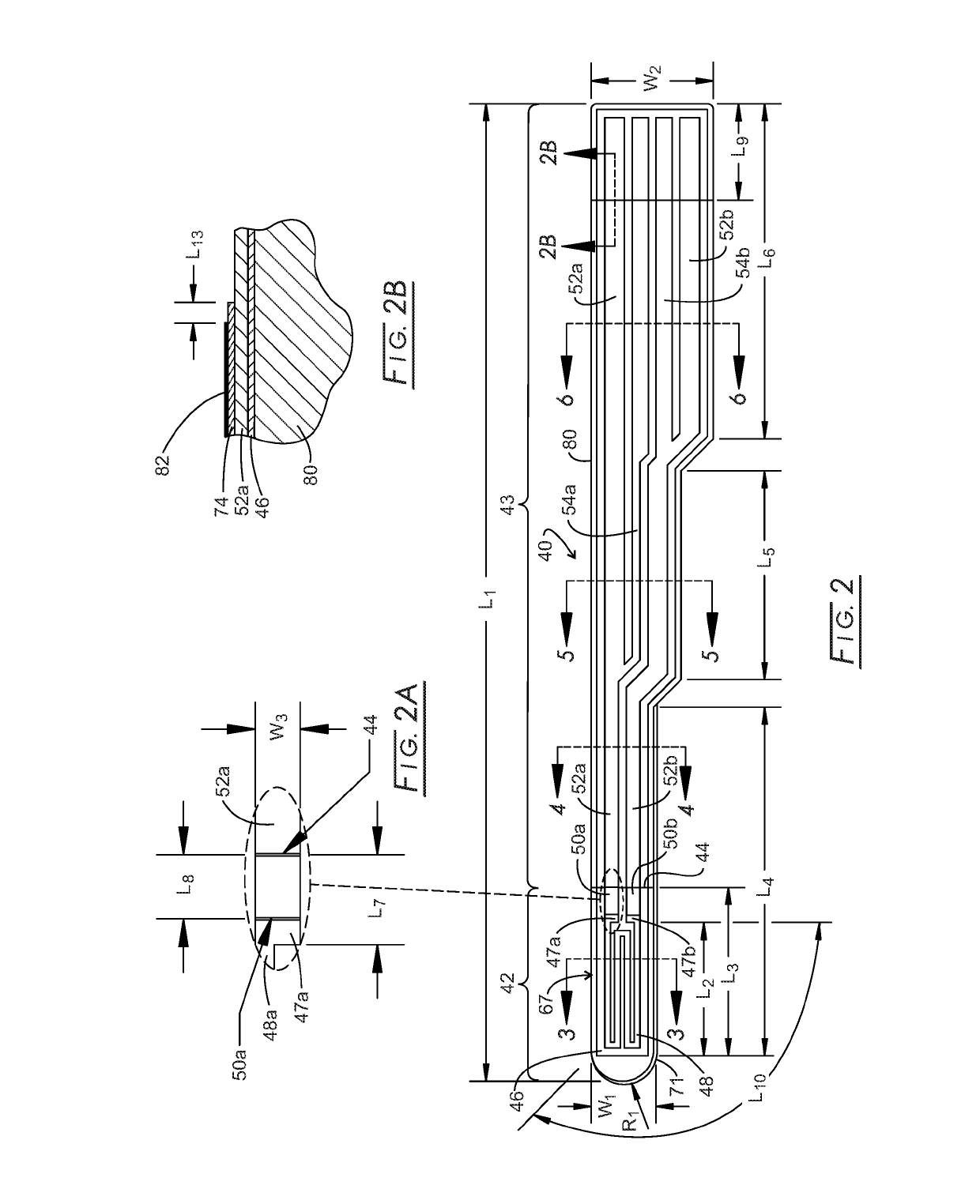
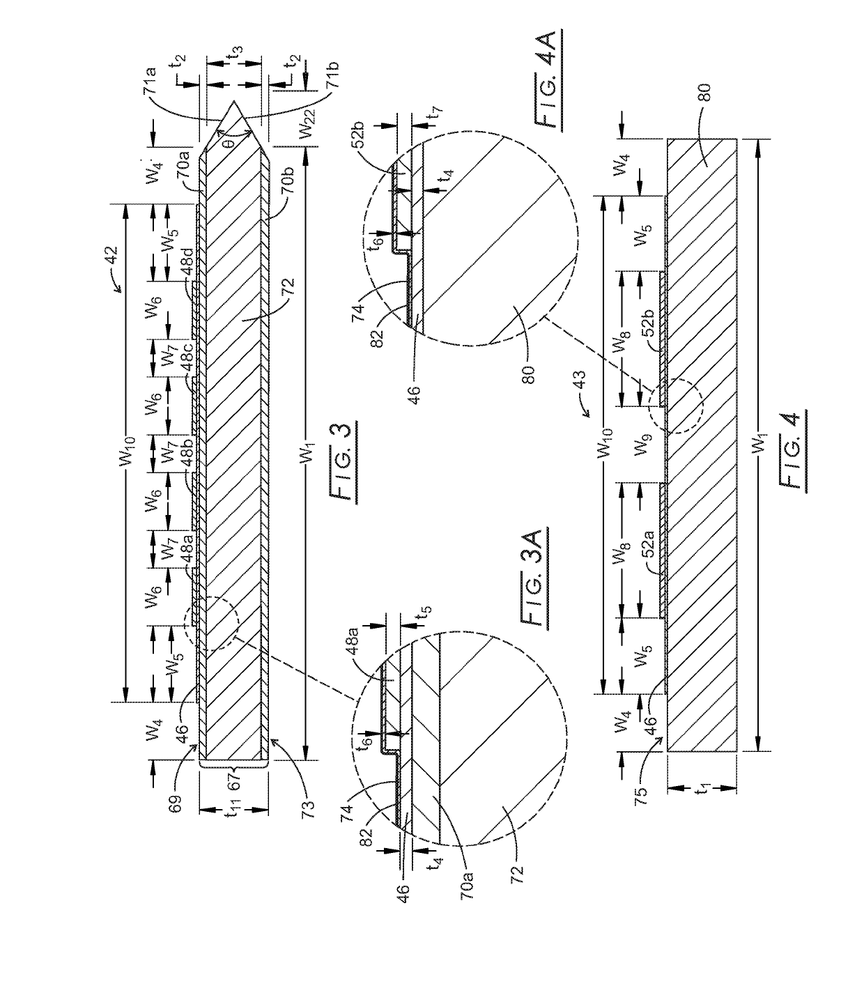
[0154]Referring to FIGS. 1, 2 and 3 and by way of example of one preferred design, the dimensions L2, L3, L4, L5, L6, W1, W2, t1, t2 and t11 of blade 40 are 0.340, 0.430, 0.870, 0.530, 0.860, 0.180, 0.350, 0.024, 0.0015 and 0.027 inches, respectively. The core 72 of first substrate 67 in heated portion 42 is silver (minimum 99% silver) and first cladding 70a and second cladding 70b are both stainless steel 430. The support member portion 43 comprises stainless steel 430 throughout. Based on [a] a preselected temperature of 500 C for the electrically resistive heating element 48 for the purposes of incision of tissue and sealing of transected blood vessels during surgery and [b] an assumed duty cycle of 50% (i.e., the fraction of time during surgery procedure that the electrically resistive heating element 48 of blade 40 is at preselected temperature), the total amount of heat that is conducted from the heater portion 42 of blade to handpiece 10 through support member portion 43 is o...


PUM


Abstract

Thermal cutting surgical instruments incorporate a blade incorporating a first substrate of high thermal conductivity material in the heated portion of the blade and a support and, the first substrate of high thermal conductivity material joined to a second substrate of low thermal conductivity material in the support region of the blade; an electrically insulative dielectric layer disposed on the first surface of the first substrate and on the first surface of second substrate; an electrically resistive heating element disposed on the electrically insulative dielectric; electrically conductive power leads and electrically conductive sense leads disposed on the electrically insulative dielectric layer and that are in electrical communication with the electrically resistive heating element; and an electrically insulative dielectric overcoat layer disposed on the electrically resistive heating element and on the distal portion of the electrically conductive power leads and electrically conductive sense leads.

Description

CROSS-REFERENCE TO RELATED APPLICATIONS[0001]This application claims benefit of provisional application 62 / 566,565 filed Oct. 2, 2017.STATEMENT REGARDING FEDERALLY SPONSORED RESEARCH[0002]Not applicable.BACKGROUND[0003]The control of bleeding during surgery accounts for a major portion of the time involved in an operation. In particular, bleeding that occurs when tissue is incised obscures the surgeon's vision, delays the operation, and reduces the precision of cutting. In addition, blood loss from the patient during surgery must be minimized to reduce or eliminate the need for supplementary blood transfusions.[0004]Conventional surgical procedures are carried out utilizing a sequence of surgical instruments or tools. At the outset of a given procedure, sharp mechanical devices, such as a scalpel, are employed to part the skin layers so as to provide external access to the body cavity. Bleeding during such initial stages may be controlled through the use of ties, clamps, blotting pr...

Claims


Application Information

Patent Timeline
Patent Type & Authority Applications(United States)
IPC IPC(8): A61B18/10A61B18/08A61B18/14
CPCA61B18/10A61B18/082A61B18/14A61B2018/1412A61B2018/00089A61B2018/00601A61B2018/00095A61B2018/00101A61B2018/00428A61B2018/00714A61B2018/00875
Inventor EGGERS, PHILIP E.
Owner EGGERS & ASSOC LLC
Why Eureka
Try Eureka