
Fixing structures and supporting structures of ceramic susceptors, and supporting members thereof

a technology of fixing structure and supporting structure, which is applied in the direction of chucks, drying solid materials, drying machines, etc., can solve the problems of easy induced fine cracks or gas leakage in the joining portion, and achieve the effect of reducing the temperature distribution, reducing the wall thickness, and increasing the temperature distribution on the heating face of the susceptor

Active Publication Date: 2005-12-27
NGK INSULATORS LTD
View PDF4 Cites 6 Cited by
  • Summary
  • Abstract
  • Description
  • Claims
  • Application Information

AI Technical Summary

Benefits of technology

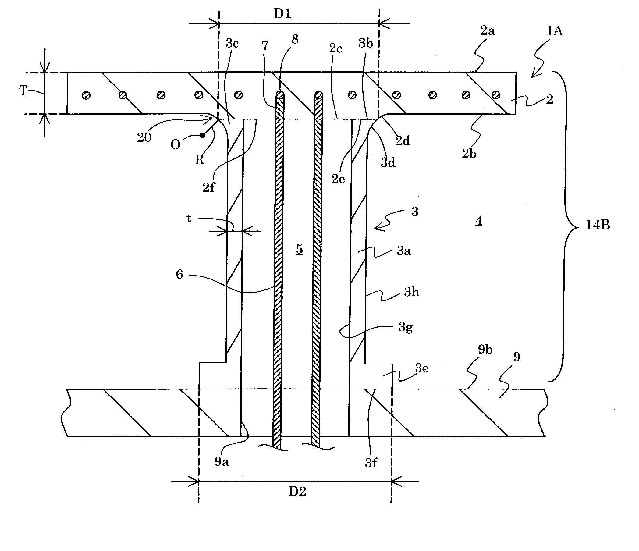
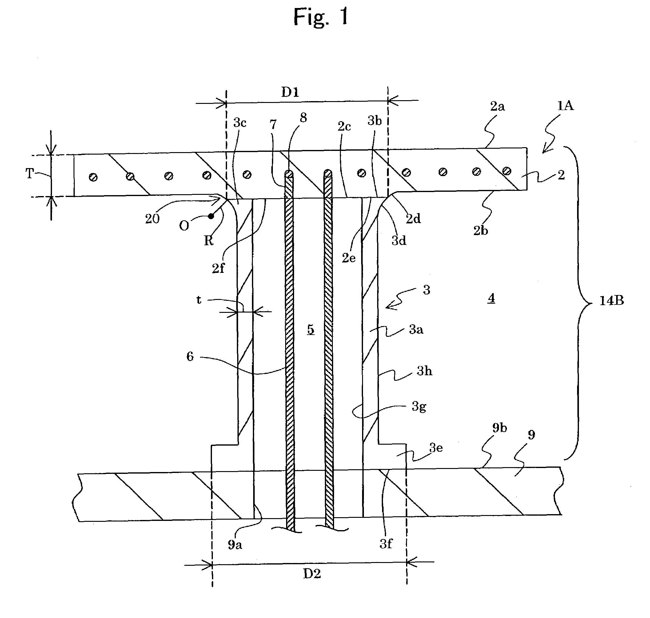
[0007]The present inventors have studied to develop a design for reducing the temperature distribution on the surface or heating face of a ceramic susceptor. When a large amount of heat is conducted from the susceptor to the supporting member through its back face, the temperature distribution on the heating face of the susceptor is increased. It is considered effective to reduce the wall thickness of the supporting member for reducing the amount of heat conducted from the susceptor through the supporting member to a chamber. When the susceptor is operated at a high temperature or its temperature is elevated, however, a thermal stress is applied onto the joining portion of the supporting member and susceptor. If the thickness of the supporting member is reduced as described above, the structural strength is reduced. Fine cracks or gas leakage may thereby be easily induced in the joining portion due to the thermal stress applied onto the joining portion. It is thus demanded to provide a novel supporting structure of a ceramic susceptor so that the temperature distribution on the susceptor may be reduced. It is also demanded, in the structure, to prevent the fine cracks or gas leakage in the joining portion, even when the susceptor is operated under severe condition such as a rapid temperature rise from room temperature to a high temperature.
[0008]An object of the present invention is, in a supporting structure of a ceramic susceptor, to reduce thermal conduction from a ceramic susceptor to a supporting member, to reduce thermal stress in the joining portion of the susceptor and supporting member, and to prevent fine cracks or gas leakage in the joining portion.
[0012]According to the present invention, it is possible to minimize thermal conduction from the susceptor through the supporting member and temperature distribution on the susceptor. Furthermore, a ceramic susceptor may be operated under severe condition, for example, the susceptor is operated at a high temperature or its temperature is rapidly elevated. Even in such case, the present invention may provide a supporting structure so that fine cracks or gas leakage in the joining portion of the susceptor and supporting member may be prevented.

Problems solved by technology

Fine cracks or gas leakage may thereby be easily induced in the joining portion due to the thermal stress applied onto the joining portion.

Method used


Image

  • Fixing structures and supporting structures of ceramic susceptors, and supporting members thereof
  • Fixing structures and supporting structures of ceramic susceptors, and supporting members thereof
  • Fixing structures and supporting structures of ceramic susceptors, and supporting members thereof

Examples


examples

[0061](Experiment A)

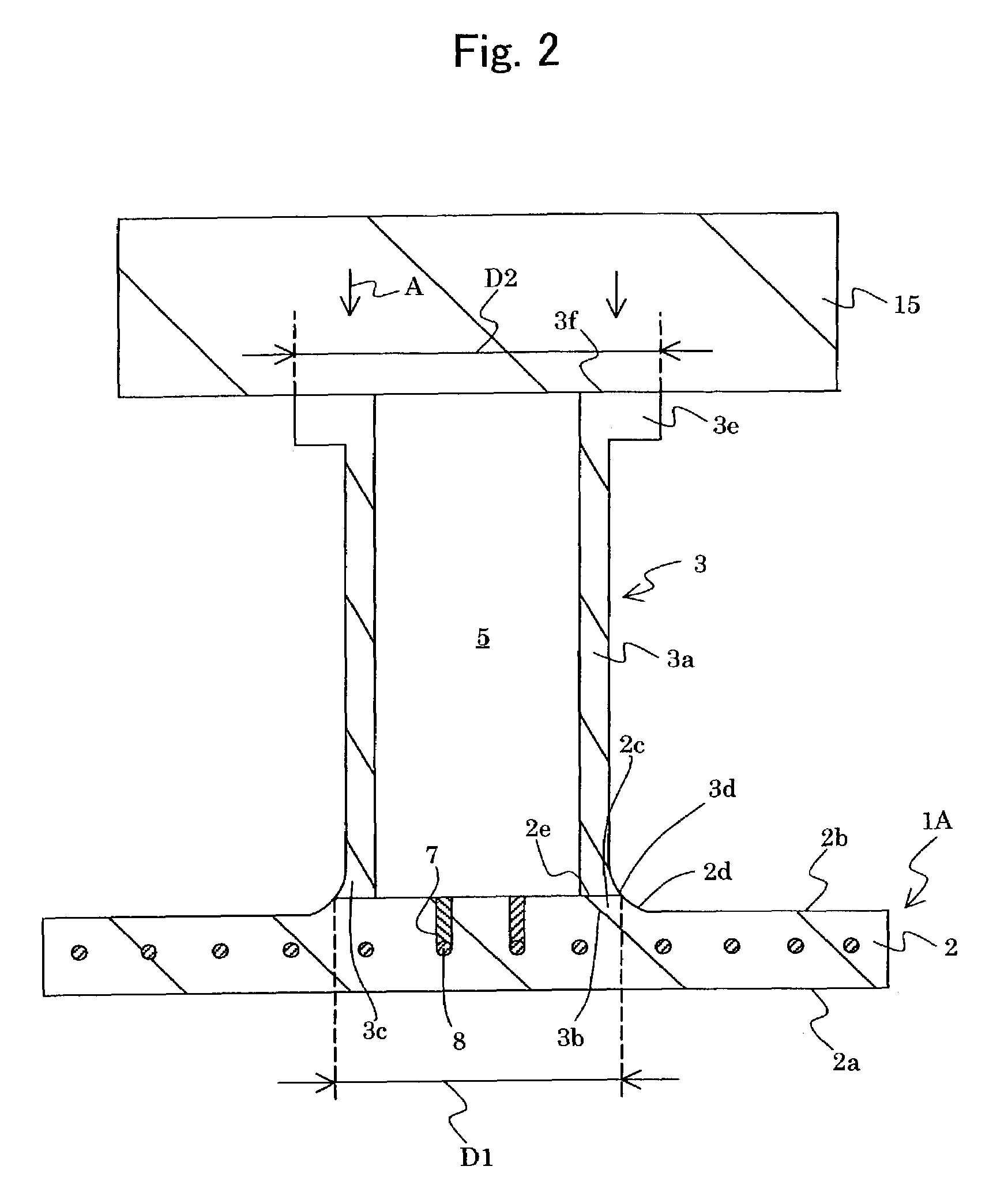
[0062]A fixing structure shown in FIG. 1 was produced. As a susceptor 1A, a disk of aluminum nitride sintered body having a diameter φ of 300 mm and a thickness of 10 mm was used. The supporting member 3 was formed of a ceramic plate. The length of the supporting member 3 was 70 mm. The supporting member 3 and susceptor 1A were set as shown in FIG. 2 by means of solid phase welding under the following condition.[0063]Pressure of atmosphere in a furnace: 0.5 kg / cm2G[0064]Maximum temperature: 2000° C.[0065]Holding time at a maximum temperature: 60 minutes[0066]Pressure during the joining process: 0.5 to 1.0 kg / cm2 [0067]Joining material: solution containing yttrium and acetic acid as main components

[0068]The supporting member 3 and chamber 9 were fixed by screws. The supporting member 3 and chamber 9 were sealed with an O-ring made of fluorine rubber.

[0069]Simulation was performed at this stage under the provision that the heating face 2a of the susceptor 1A was he...


PUM

PropertyMeasurementUnit
Lengthaaaaaaaaaa
Lengthaaaaaaaaaa
Lengthaaaaaaaaaa

Abstract

A supporting structure of a ceramic susceptor is provided, including a ceramic susceptor to be heated having a mounting face and a back face, and a ceramic supporting member joined with the back face of the susceptor. The supporting member has an outer wall surface, and a continuous and integral curved part formed between the outer wall surface and the back face of the susceptor. The curved part has a radius of curvature “R” in a range of 4 mm to 25 mm in the longitudinal direction of the supporting member, and a minimum wall thickness “t” in a range of 1 mm to 15 mm.

Description

[0001]This application claims the benefit of Japanese Patent Application P2002-90330 filed on Mar. 28, 2002, the entirety of which is incorporated by reference.BACKGROUND OF THE INVENTION[0002]1. Field of the Invention[0003]The present invention relates to a fixing structure of a ceramic susceptor to a chamber, a supporting structure of a ceramic susceptor and a supporting member for the same.[0004]2. Related Art Statement[0005]In a system for producing semiconductors, it is necessary to fix a ceramic susceptor made of, for example, aluminum nitride to the inner wall surface of a chamber. For this, one end of a tubular supporting member made of a ceramics is fixed to a joining face of a ceramic heater and the other end is fixed to the inner wall surface of a chamber. The supporting member is composed of a ceramic plate made of a heat resistant ceramics such as alumina and aluminum nitride. The supporting member and chamber are sealed with an O-ring to secure the air-tightness. It is...

Claims


Application Information

Patent Timeline
IPC IPC(8): C23C16/00H01L21/00H01L21/683H01L21/02H01L21/306H01L21/68H01L21/687
CPCC04B37/005H01L21/68792B32B2315/02Y10T279/23C04B2237/066
Inventor YAMAGUCHI, KAZUAKIGOTO, YOSHINOBU
Owner NGK INSULATORS LTD
Learn More