Exhaust heat recovery apparatus

a technology for exhaust heat recovery and exhaust heat, which is applied in the direction of lighting and heating equipment, machines/engines, greenhouse gas reduction, etc., can solve the problems achieve the effect of improving the mountability of the exhaust heat recovery apparatus on the vehicle, and reducing the exhaust heat recovery efficiency

Inactive Publication Date: 2008-12-02
TOYOTA JIDOSHA KK
View PDF23 Cites 2 Cited by
  • Summary
  • Abstract
  • Description
  • Claims
  • Application Information

AI Technical Summary

Benefits of technology

[0009]This exhaust heat recovery apparatus is installed in a heat medium passage so that a device installing surface formed in the heat medium passage is in parallel to a heater connecting side end surface and a cooler connecting side end surface of a cylinder. Due to the above-described structure, the pipe lengths of the cooler become the same and the pipe lengths of the regenerator become the same, thereby reducing the temperature distribution of the working fluid to be introduced from the cooler into a second cylinder. As a result, the exhaust heat recovery apparatus can be installed in, for example, the exhaust passage of the internal combustion engine and the exhaust passage of factory exhaust heat as restraining reduction in exhaust heat recovery efficiency.
[0029]Also, the exhaust heat recovery apparatus according to the present invention is installed in the heat medium passage with the first cylinder to be connected to the heater being arranged at an upstream side on the heat source medium. Accordingly, since the working fluid heated by the heat source medium with high temperature is introduced in the first cylinder, exhaust heat recovery efficiency increases, and the exhaust heat recovery apparatus can be installed in, for example, the exhaust passage of the internal combustion engine and the exhaust passage of the factory exhaust heat.

Problems solved by technology

Yet, depending upon how the Stirling engine is installed in the exhaust passage of the internal combustion engine and the exhaust passage of the factory exhaust heat, the heater (heating portion) and cooler (cooling device) cannot often be set effectively, which sometime results in reduction of the exhaust heat recovery efficiency.

Method used


Image

  • Exhaust heat recovery apparatus
  • Exhaust heat recovery apparatus
  • Exhaust heat recovery apparatus

Examples


Embodiment Construction

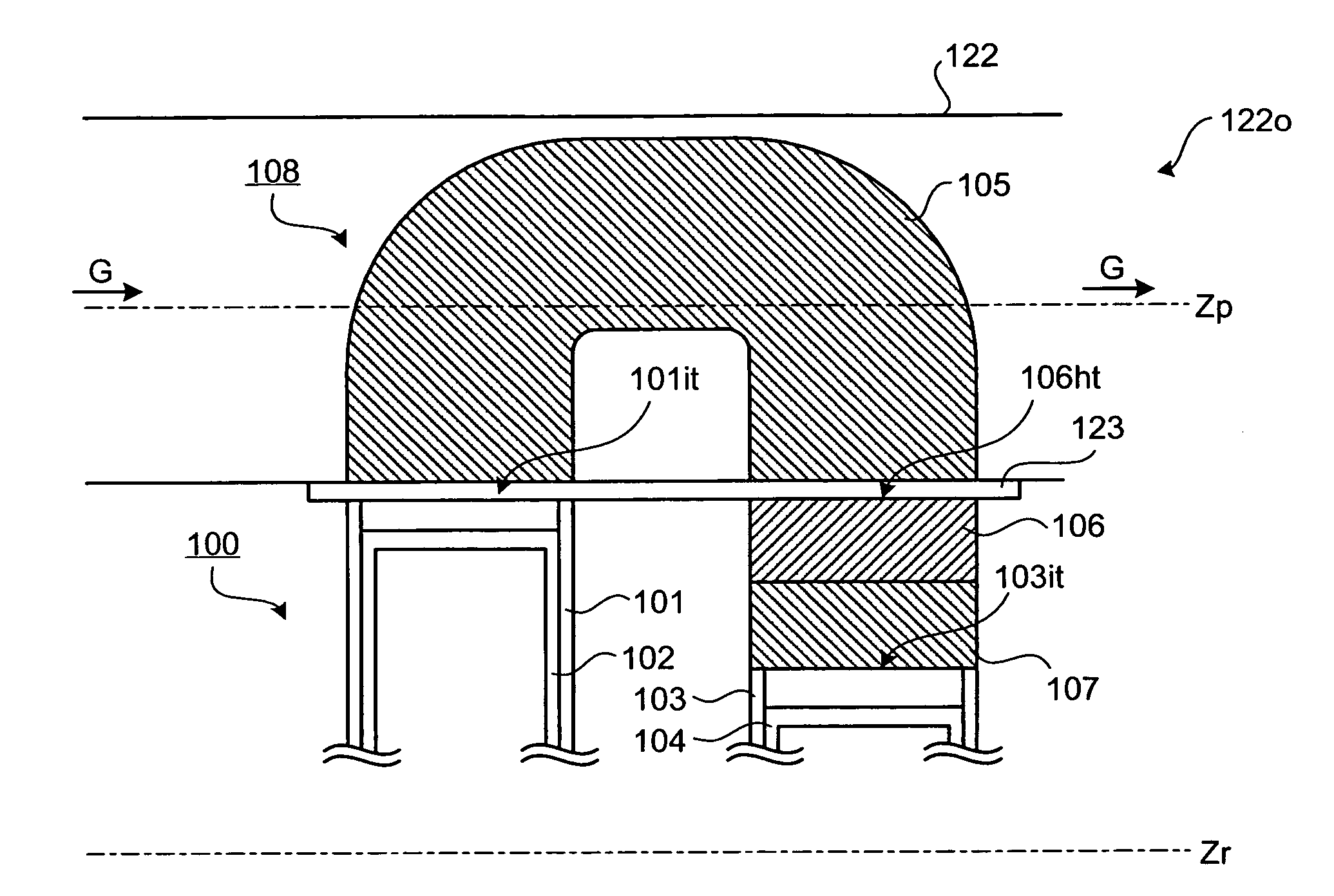
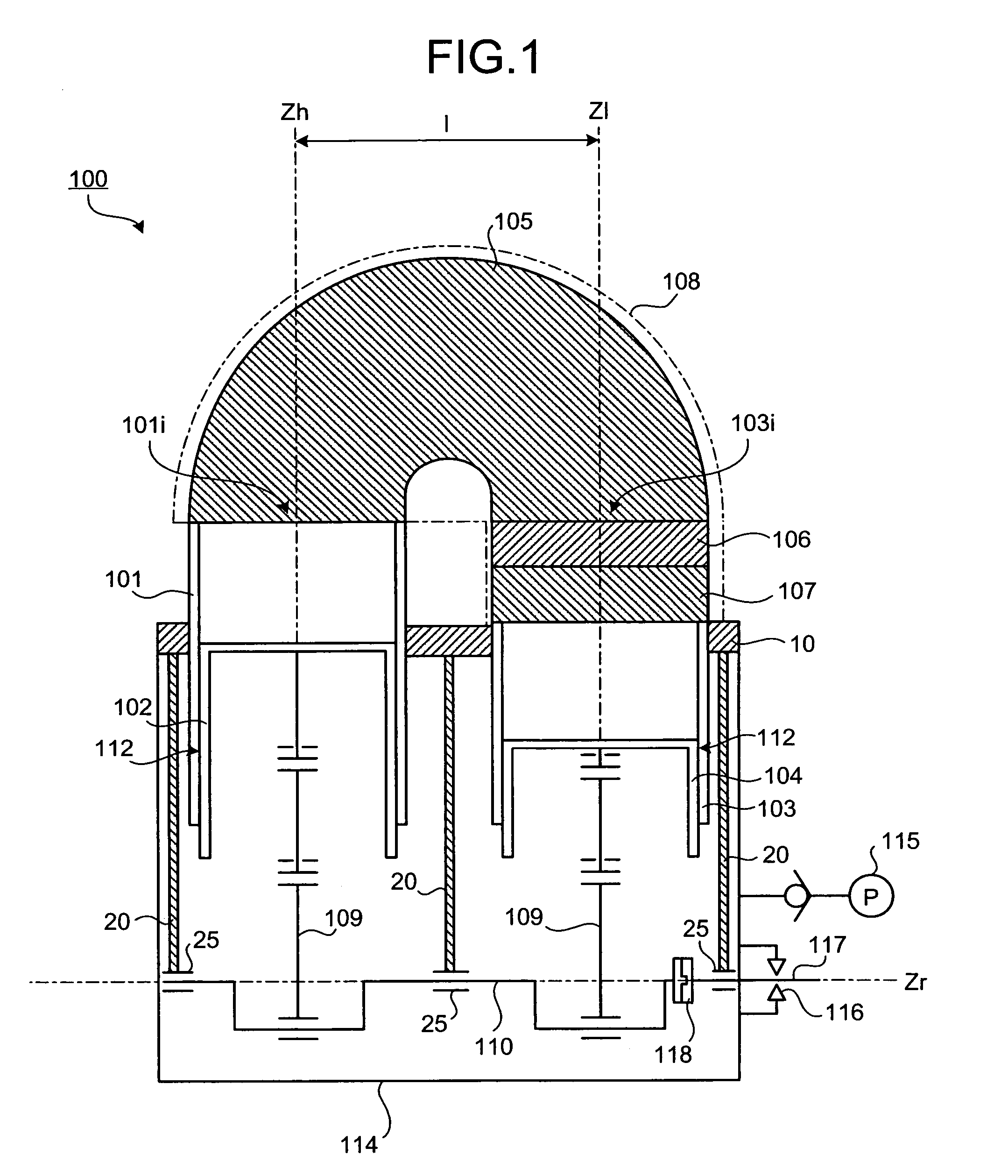
[0048]Embodiments of the invention will be explained in detail below with reference to the accompanying drawings. Furthermore, the invention is not limited by the preferred embodiments explained herein. Also, components of the following preferred embodiments may include one that is apparent to those skilled in the art or practically identical to the components herein. Still further, the following explanation uses an example where the Stirling engine is used as the exhaust heat recovery apparatus for recovering the exhaust heat of the internal combustion engine; however, the exhaust heat recovery object is not limited to the internal combustion engine, and the invention can be employed in, for example, the exhaust heat recovery for a factory, a plant, or a power plant.

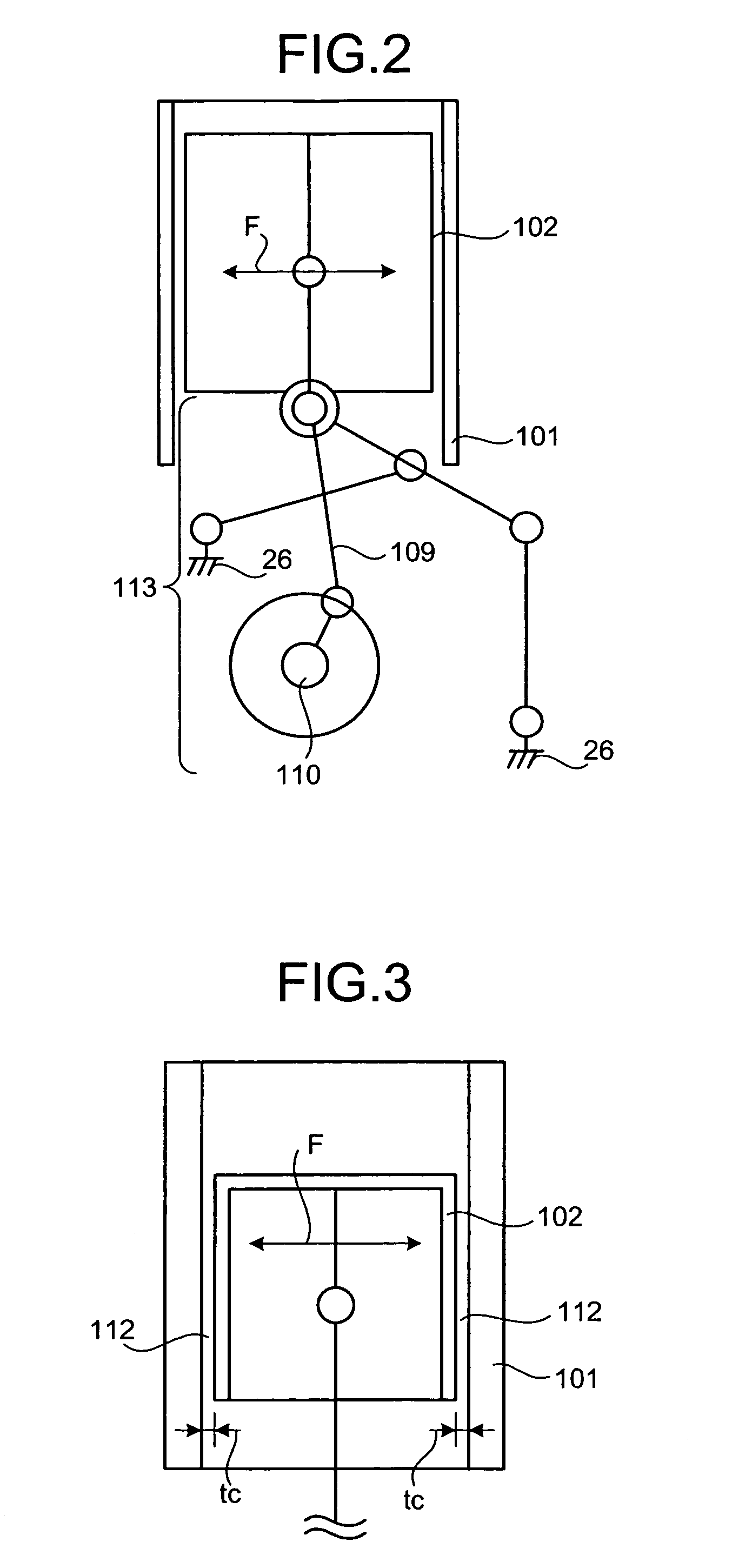
[0049]FIG. 1 is a cross-section view of the Stirling engine according to the present invention. FIG. 2 is a cross-section view of the high temperature side piston viewed from the direction parallel to the crank shaft. F...


PUM


Abstract

An exhaust heat recovery apparatus (functioning as a Stirling engine), which is installed in, for example, an exhaust passage of an internal combustion engine and an exhaust passage of factory exhaust heat as restraining reduction in exhaust heat recovery efficiency, is installed in a device installing surface formed in the heat medium passage so that the device installing surface and a heater connecting side end surface of a high temperature side cylinder become parallel and the device installing surface and a cooler connecting side end surface of a low temperature side cylinder become parallel. The high temperature side cylinder is arranged at an upstream side of a direction of exhaust flow. The low temperature side cylinder is arranged at a downstream side of the high temperature side cylinder.

Description

[0001]This is a Continuation of Application No. PCT / JP2004 / 013952 filed Sep. 24, 2004, which claims the benefit of Japanese Patent Application No. 2003-343417 filed Oct. 1, 2003. The entire disclosure of the prior application is hereby incorporated by reference herein in its entirety.BACKGROUND OF THE INVENTION[0002]1. Field of the Invention[0003]The present invention relates to an exhaust heat recovery apparatus, and more particularly to the exhaust heat recovery apparatus which can be installed in, for example, an exhaust passage of an internal combustion engine and an exhaust passage of factory exhaust heat as restraining reduction in exhaust heat recovery efficiency.[0004]2. Description of the Related Art[0005]Recently, in order to recover the exhaust heat of the internal combustion engine mounted on vehicles such as a passenger car, bus, and truck and the factory exhaust heat, Stirling engine with excellent theoretical thermal efficiency has received attention. Japanese Utility...

Claims


Application Information

Patent Timeline
Patent Type & Authority Patents(United States)
IPC IPC(8): F02G3/00F02G1/044F02G1/055F02G5/02F28D21/00
CPCF02G5/02F28D21/0003F02G2254/15Y02T10/166Y02E20/30Y02T10/12Y02P80/10
Inventor YAGUCHI, HIROSHISAWADA, DAISAKU
Owner TOYOTA JIDOSHA KK
Why Eureka
Try Eureka