
Cooling apparatus and a thermostat with the apparatus installed therein

a technology of thermostats and cooling apparatuses, which is applied in the direction of domestic cooling apparatus, lighting and heating apparatus, refrigeration components, etc., can solve the problems of difficult to meet the severe requirements, the temperature of the ‘hunting’ portion, and the rise of a certain problem, so as to improve the accuracy of temperature control, reduce the temperature distribution in the room, and save construction costs

Inactive Publication Date: 2008-08-26
ENOMOTO SHINICHI
View PDF17 Cites 3 Cited by
  • Summary
  • Abstract
  • Description
  • Claims
  • Application Information

AI Technical Summary

Benefits of technology

This configuration stabilizes temperature distribution, reduces energy consumption, and eliminates the need for supplementary cooling systems, achieving precise temperature control within a wide range without noticeable fluctuations, thus enhancing the efficiency and cost-effectiveness of cooling systems.

Problems solved by technology

The on-off control of the compressor for keeping the temperature of ambient load-contacting portions close to the target temperature has however given rise to a certain problem.
Such a simple mode of control has often caused fluctuation or ‘hunting’ of said portions' temperature.
However, such an on-off control of compressors as summarized above will fail to realize a sufficient stability in temperature of the coolers' portions in contact with ambient load, with a resultant significant fluctuation in temperature of the object to be controlled, making it difficult to meet the severe requirement.
Some of those plants are therefore equipped with highly responsible heaters in addition to the coolers so that an excessive degree of cooling is canceled with heat which those heaters will emit.
This approach to diminish the problem inherent in the former systems does however include a contradiction that cooling is done on one hand and heating is done simultaneously on the other hand, thus lowering efficiency of energy and failing to save energy.
One of the most important requirements to the environmental testers and the like is that temperature distribution in each of them should be as small as possible, but the former apparatuses have not been satisfactory from this point of view.
As a result, temperature will become non-uniform even by means of the evaporator itself included in this type of coolers, thereby producing an unallowable temperature distribution throughout the ambient load, which disables accurate environmental tests.
However, such a countermeasure necessitating its own circuit, circulating pumps and other devices for the supplementary coolant will render the cooler expensive and make the cooler too large in scale to be accommodated in a given space not so wide.
In addition to these principal devices, a reservoir 105 is indispensable in such a proposal and will further need an electric heater 106 immersed therein, thus raising an equipment cost, occupying a larger space and unreasonably lowering thermal efficiency.

Method used


Image

  • Cooling apparatus and a thermostat with the apparatus installed therein
  • Cooling apparatus and a thermostat with the apparatus installed therein
  • Cooling apparatus and a thermostat with the apparatus installed therein

Examples


first embodiment

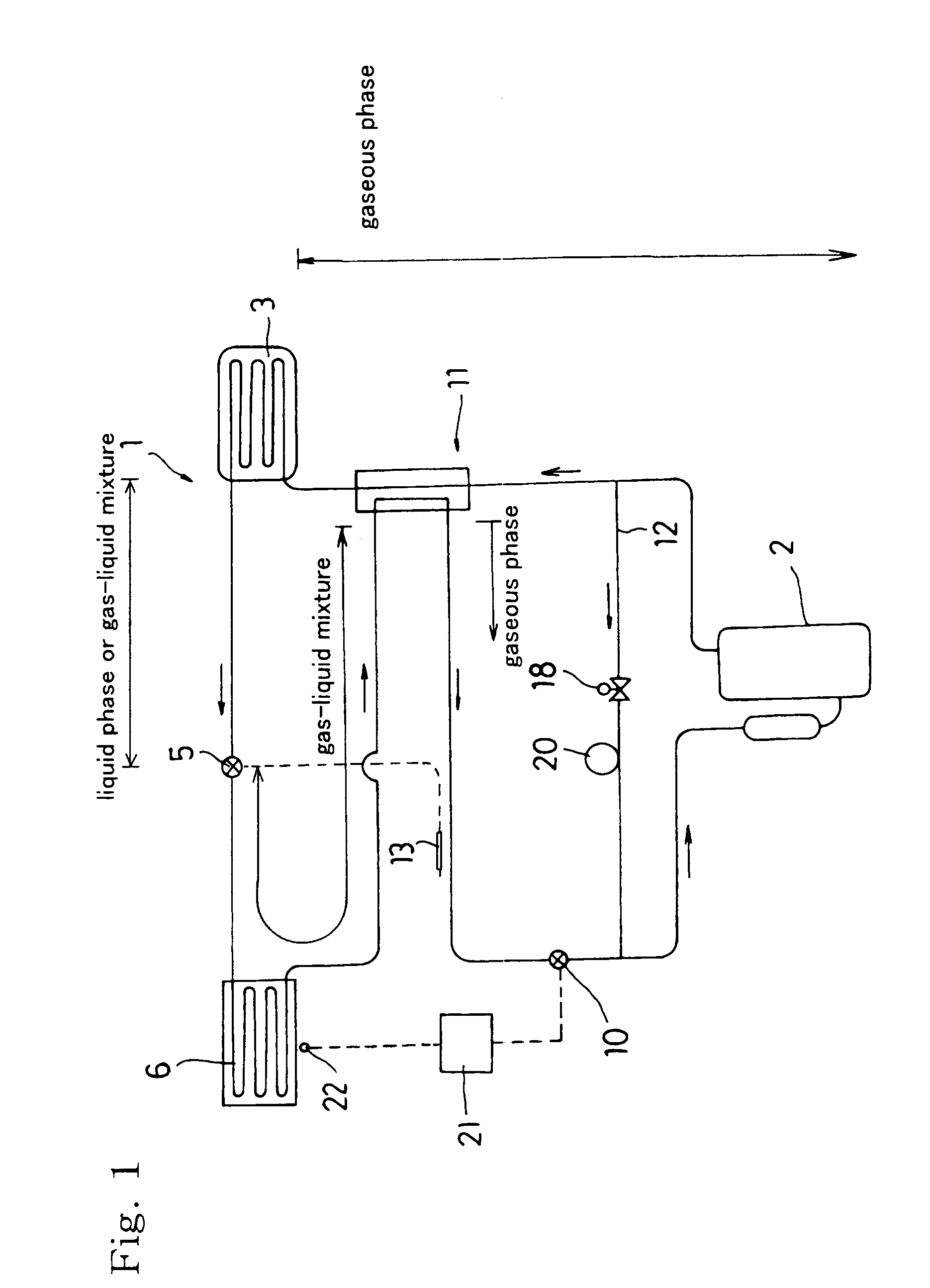
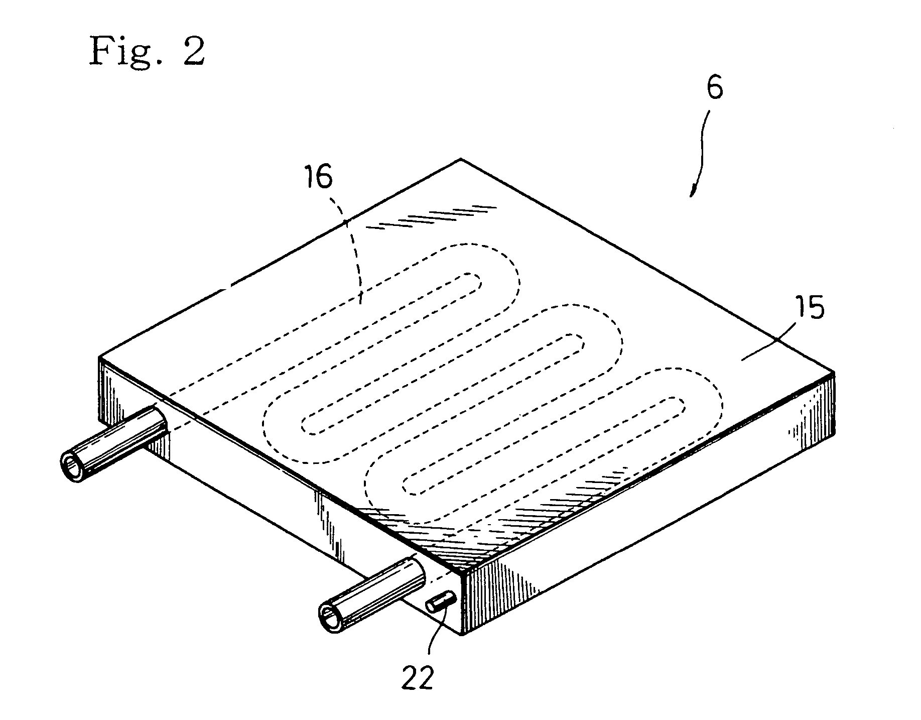
[0082]FIG. 1 illustrates a cooling apparatus 1 (hereinafter simply referred to as ‘cooler’, sometimes) provided in a This cooler 1 may be used to test the environmental performance of semiconductors or the like.

[0083]Similarly to the former type coolers, this cooler 1 includes a compressor 2, a condenser 3, an expansion valve 5 and an evaporator 6. In addition to these devices, the cooler 1 further includes an electric valve 10 so that they are connected one to another to form a refrigeration circuit. Peculiar to this cooler, it has built therein a heating section (viz., heat exchanging section) 11 and a bypass 12.

[0084]The compressor 2 is a pump for compressing a refrigerant vapor, and this pump is of the reciprocation type, the rotary type or the scrawl type as in the prior art compressors.

[0085]The condenser 3 is a heat exchanger constructed to cool the refrigerant vapor flowing therethrough, using an air stream supplied from a fan not shown.

[0086]The expansion valve 5 is the so...

second embodiment

[0133]The heating section 11 adopted in this embodiment utilizes the refrigerant mass on the high-pressure side defined between the upstream compressor 2 and the downstream condenser 3. Such a mass will heat the other mass on the low-pressure side defined between the outlet of evaporator 6 and the downstream electric valve 10. However, the present invention is not delimited to this embodiment, but may employ in place of the heating section 11 an electric heater 23 disposed on said low-pressure side to heat the mass flowing therethrough, as in a second embodiment shown in FIG. 5. This heater 23 always energized with an electric current of a sufficient power is preferably of a capacity enough to assure the necessary degree of superheating.

[0134]Though the heat source 11 in the embodiment shown in FIG. 1 is a stream of refrigerant flowing within the higher-pressure side, downstream of its compressor 2 and upstream of its condenser 3, the heat source 11 may be a stream of refrigerant fl...

third embodiment

[0141]FIG. 7 shows a cooler formed as a temperature chamber 33 with a thermostat-like mechanism, which cooler 30 is provided in accordance with a The same reference numerals are allocated to parts corresponding to those in the preceding embodiments, in order not to repeat description thereof.

[0142]The cooler 30 illustrated in FIG. 7 does also include a compressor 2, a condenser 3, an expansion valve 5, an evaporator 35 and an electric valve 10. These devices are connected one to another in this order to form a refrigeration circuit, in which a heating section 11 is disposed similarly to the first embodiment.

[0143]The evaporators 6 in the preceding embodiments are each a direct-expansion plate-type heat exchanger, which cools the object by heat conduction through contact between the object and the plate. However, the evaporator 35 employed in the third embodiment is a pipe coil type or a finned coil type similar to those included in the conventional air conditioners and refrigerator...


PUM


Abstract

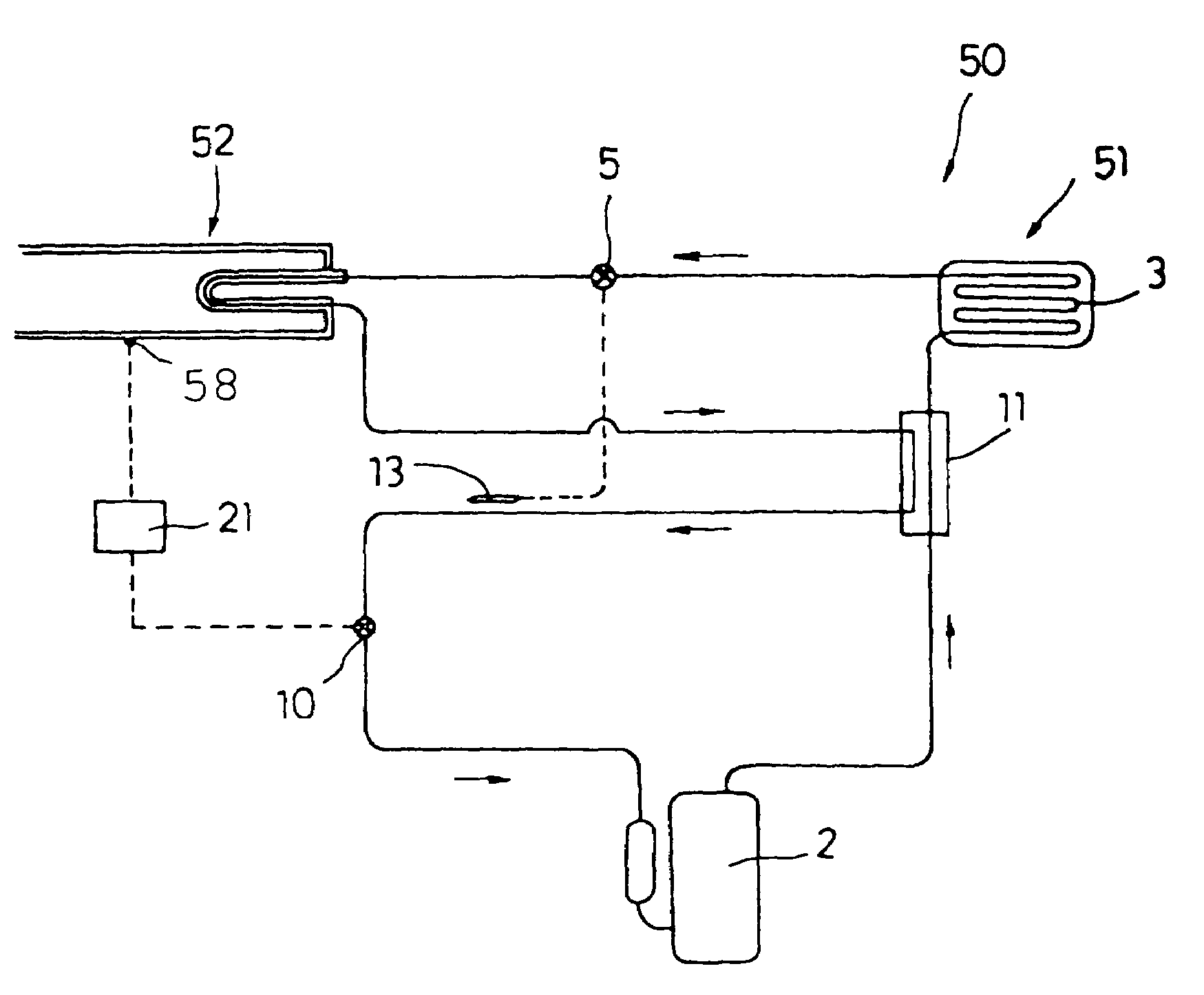
A cooling apparatus (1) has a compressor (2), a condenser (3), an expansion valve (5), an evaporator (6) and an electric valve (10), all connected to each other in this order by a piping line to form a refrigeration circuit. The apparatus further has a heating section (11) and a bypass (12), and a thermosensitive tube (13) of the expansion valve is disposed between the heating section (11) and the electric valve (10) so that temperature of a refrigerant having left this section is detected before entering this valve (10). The refrigerant remains as a gas-liquid mixture until it leaves the evaporator (6) such that temperature of the refrigerant is uniform within the evaporator and equal to the saturation vapor temperature of this refrigerant, and therefore fluctuation in the refrigerant temperature is diminished.

Description

CROSS-REFERENCE[0001]This application is a division of Ser. No. 10 / 337,111, filed Jan. 6, 2003 now U.S. Pat. No. 6,938,432, entitled “Cooling Apparatus and a Thermostat With the Apparatus Installed Therein”.BACKGROUND OF THE INVENTION[0002]1. Field of the Invention[0003]The present invention relates to a cooling apparatus (hereinafter referred to simply and often as ‘cooler’) adapted for incorporation into a manufacture system and / or an inspection system such as designed to make, inspect and / or evaluate semiconductors, electronic devices or the like, within a space that must be kept severely at a constant temperature.[0004]2. Description of Related Art[0005]Cooling apparatuses are widely used in refrigerators, air conditioners and the like to provide lower temperatures. As well known in the art, each cooler includes a refrigeration circuit built therein such that a compressor, a condenser, an expansion valve and an evaporator are connected to each other in this order by a piping lin...

Claims


Application Information

Patent Timeline
Patent Type & Authority Patents(United States)
IPC IPC(8): F25D23/12F25B41/04F28F7/00H05K7/20F25B40/00
CPCF25B40/00F25B41/043F25B2700/2117F25B2700/2104F25B2400/0401F25B41/22
Inventor ENOMOTO, SHINICHI
Owner ENOMOTO SHINICHI
Learn More