

Fuel cell system
a fuel cell and system technology, applied in the field of fuel cell systems, can solve the problems of affecting the efficiency of fuel cells, particularly the likely rise of the temperature at the center, etc., and achieve the effects of facilitating heat transfer, promoting uniform temperature distribution in the fuel cell, and facilitating heat transfer
- Summary
- Abstract
- Description
- Claims
- Application Information
AI Technical Summary
Benefits of technology
Problems solved by technology
Method used
Image

Examples
first embodiment
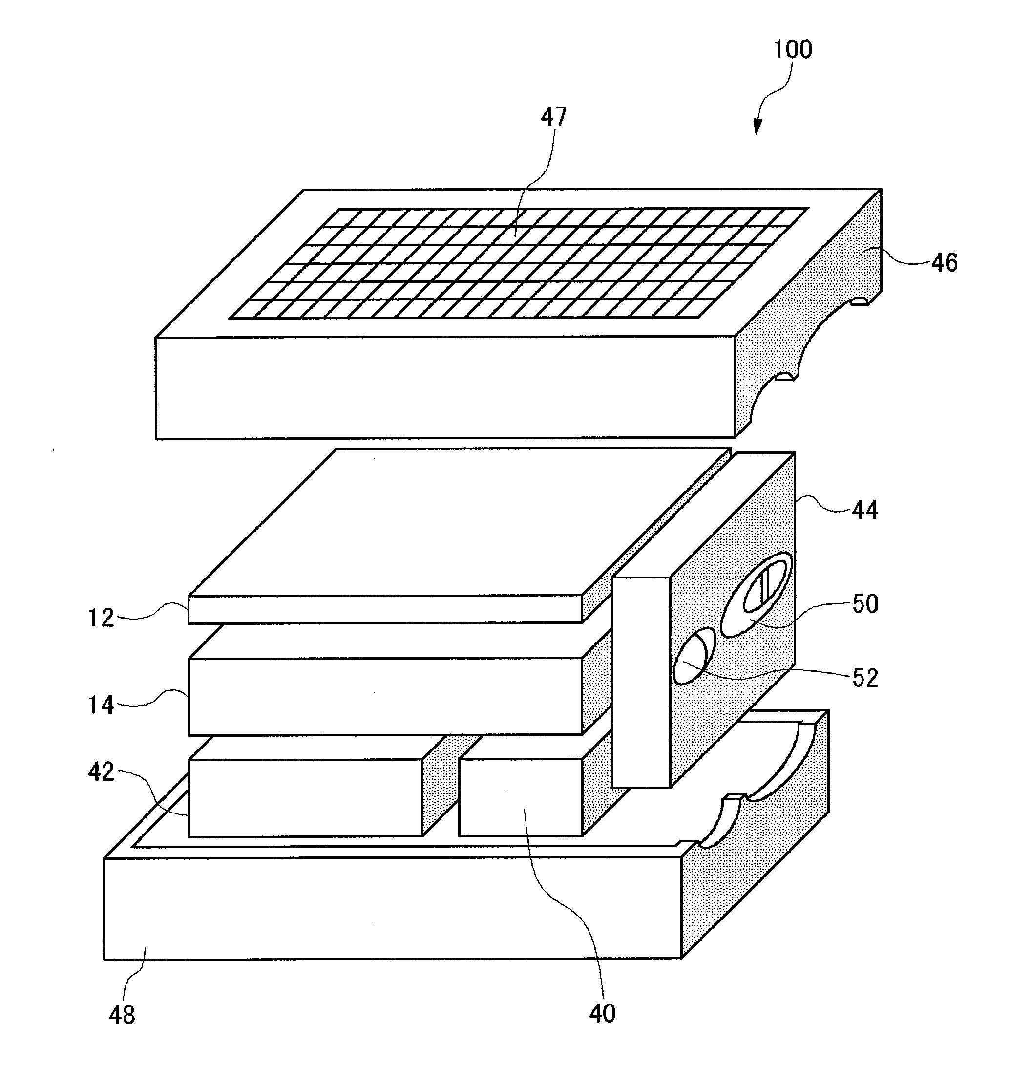
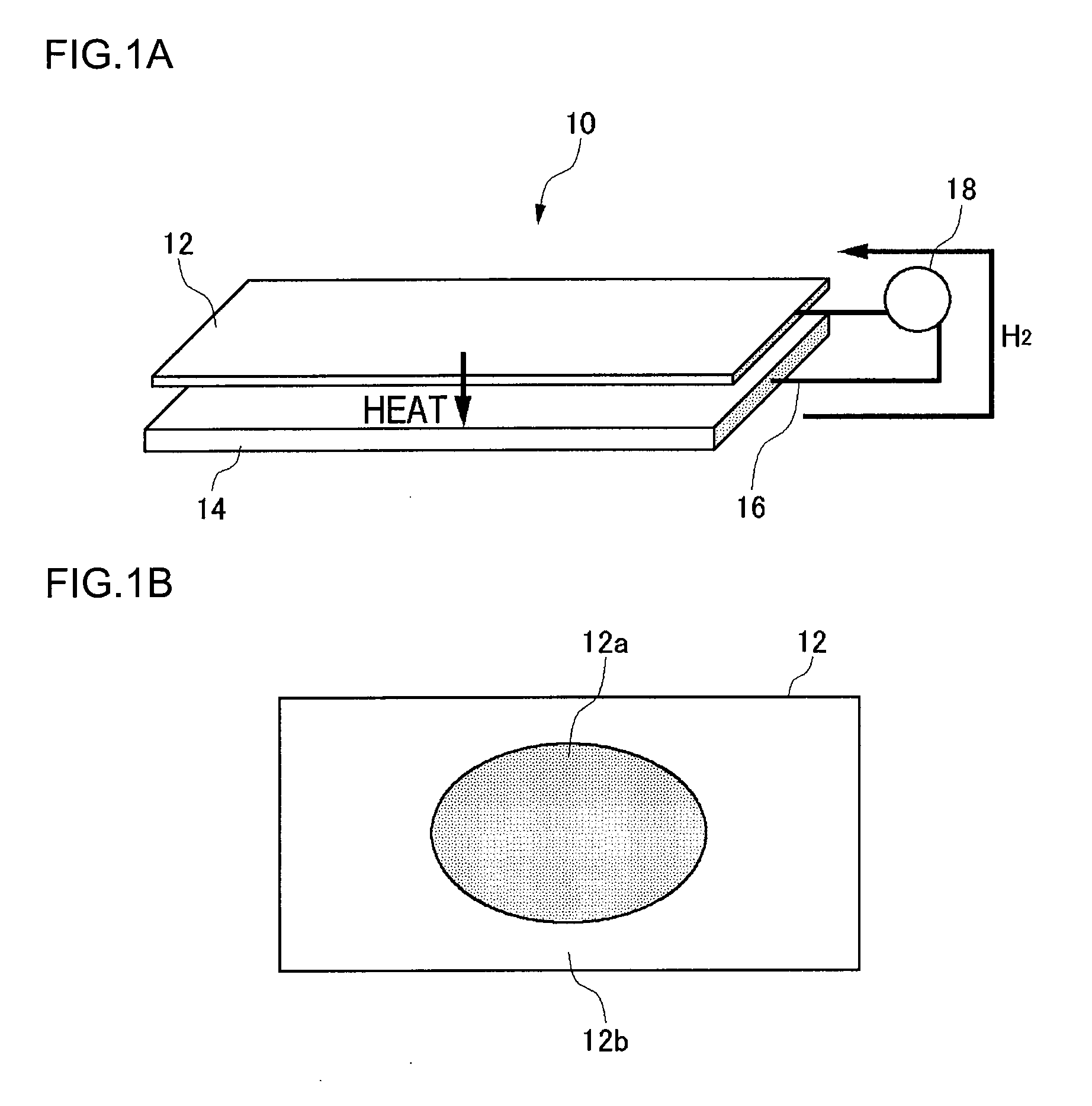
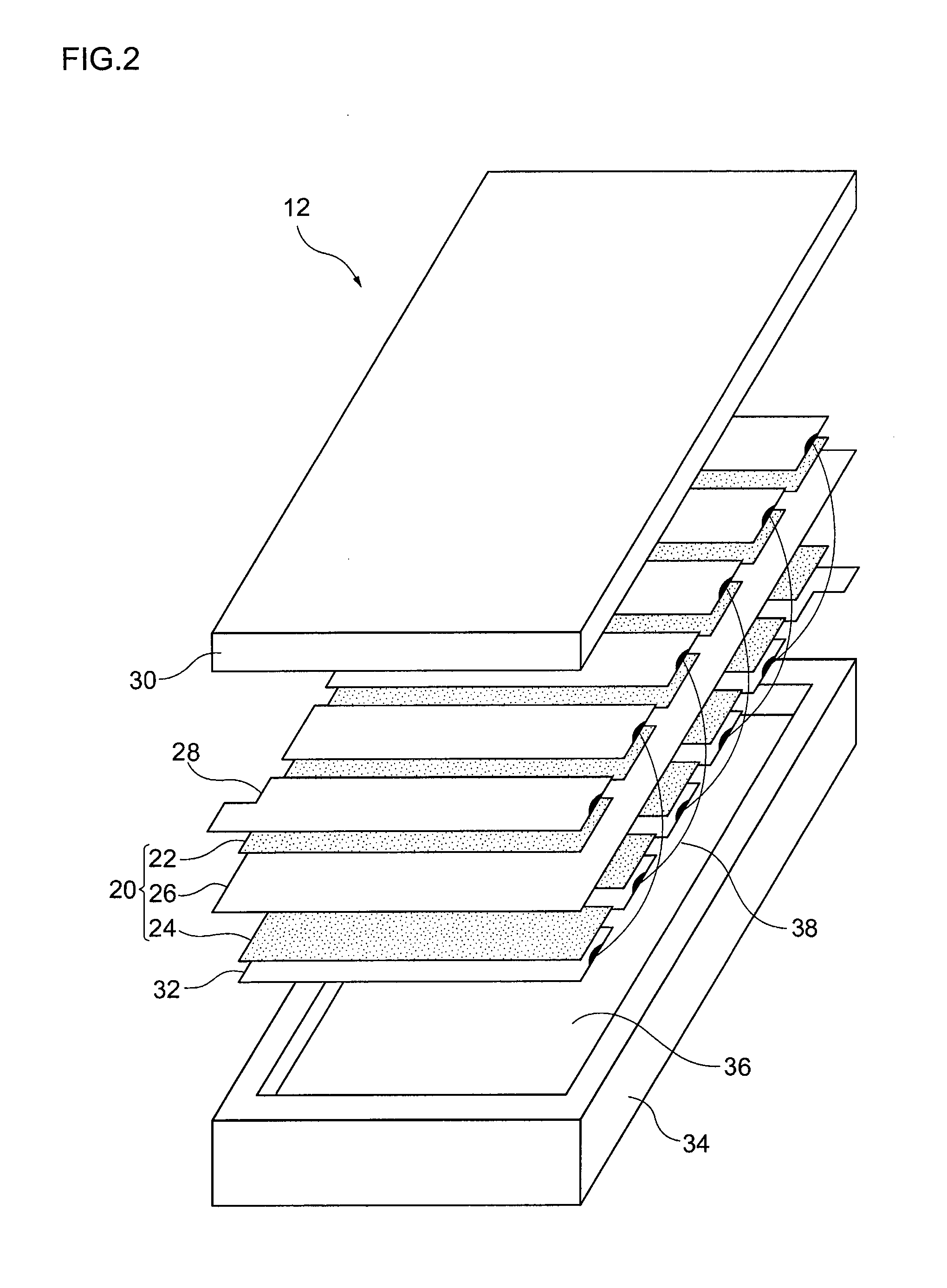
[0048]A description will first be given of heat generation occurring when a fuel cell system generates electricity. FIG. 1A is a schematic view of a fuel cell main unit and a fuel tank of a fuel cell system, and FIG. 1B is a top view showing temperature distribution in a fuel cell occurring when electricity is generated. FIG. 2 is an exploded perspective view of the fuel cell shown in FIG. 1A.
[0049]The fuel cell system 10 shown in FIG. 1A comprises a fuel cell 12, a fuel cartridge 14 provided opposite to the fuel cell 12, a supply channel 16 configured to supply hydrogen from the fuel cartridge 14 to the fuel cell 12, and a regulator (pressure reducing valve) provided in the middle of the supply channel 16. The fuel cartridge 14 contains a hydrogen absorbing alloy capable of absorbing hydrogen, which is a fuel for the fuel cell 12. The supply channel 16 supplies hydrogen discharged from the hydrogen absorbing alloy to the fuel cell 12.
[0050]As shown in FIG. 2, the fuel cell 12 compr...
second embodiment
[0080]FIG. 12 is a perspective view showing the appearance of the fuel cartridge in which a plurality of fuel tanks according to the second embodiment are arranged. The configuration of the fuel cell system according to this embodiment is the same as that of the first embodiment except for the fuel cartridge. Therefore, the description of the components other than the fuel cartridge is omitted as appropriate and it will be assumed that the system has the same configuration as that of the first embodiment unless specifically referred to.
[0081]As shown in FIG. 12, a fuel cartridge 114 according to the second embodiment is provided with a plurality of rectangular fuel tanks 154 in an arranged, and a discharging unit 154a connected to the fuel tanks 154. Each fuel tank 154 has a shape in which one of its corners 154b is cut out. The discharging unit 154a is provided in a space formed by cutting out the corners 154b of the fuel tanks 154. Thus, the fuel cartridge 114 is configured such t...
third embodiment
[0090]A filler member filling a gap between the interior surface of the housing and the hydrogen absorbing alloy is provided in the fuel tank according to the third embodiment. FIG. 15A is a perspective view showing the appearance of the fuel tank according to the third embodiment. FIG. 15B is a Y-Y cross section of the fuel tank shown in FIG. 15B. FIG. 15C is an exploded perspective view showing the essential part of the fuel tank according to the third embodiment. FIG. 16 is a cross section showing the schematic configuration of the fuel cartridge according to the third embodiment.
[0091]As shown in FIGS. 15A-16, a fuel tank 354 is provided with a housing 354b, a molded hydrogen absorbing alloy 354c contained in the housing 354b, and a filler member 354d filling a gap between the interior surface of the housing 354b and the hydrogen absorbing alloy 354c. A plurality of molded hydrogen absorbing alloy pieces 354c are arranged in the fuel tank 354. The housing 354b comprises a materi...
PUM
| Property | Measurement | Unit |
|---|---|---|
| shape | aaaaa | aaaaa |
| area | aaaaa | aaaaa |
| heat insulating | aaaaa | aaaaa |
Abstract
Description
Claims
Application Information