Method of assembling VCSEL chips on a sub-mount

a technology of vcsel chips and sub-mounts, which is applied in the direction of lasers, semiconductor lasers, basic electric elements, etc., can solve the problems of high cost and time consumption, and achieve the effect of high chip alignment accuracy

Active Publication Date: 2015-06-23
TRUMPF PHOTONIC COMPONENTS GMBH
View PDF2 Cites 1 Cited by
  • Summary
  • Abstract
  • Description
  • Claims
  • Application Information

AI Technical Summary

Benefits of technology

[0003]It is an object of the present invention to provide a method of assembling VCSEL chips on a sub-mount, which provides a high alignment accuracy of the chips without any time consuming measures.
[0008]The proposed method thus allows the alignment of the VCSEL chips on the sub-mount with a high accuracy only limited by the accuracy of defining the connecting areas, i.e. for patterning the de-wetting layer. The method does not require any expensive and time consuming active alignment.
[0012]Another metal layer is applied overlapping the p-type mesas and the p-contacts. This layer may be applied in the same step as the formation of the layer making the connection to the n-contact. This metal layer mechanically stabilizes the mesas. Since this metal layer also covers the sides of the p-type mesas, the heat conduction to the sub-mount can be improved by forming the metal layer of a highly heat conducting material, preferably of Au or Cu. This is important for a maximum efficiency and output power of VCSEL power arrays in which the thermal conduction of the VCSEL chips to the heat sink needs to be minimized. By using sub-mounts of appropriate materials with high thermal conductivity, for example of silicon, AlN or diamond with thermal conductivities of 150 W / mK or above, a very low thermal resistance to an underlying heat sink is achieved which results in a maximum efficiency of the whole VCSEL array device.

Problems solved by technology

This is an expensive and time consuming method.

Method used


Image

  • Method of assembling VCSEL chips on a sub-mount
  • Method of assembling VCSEL chips on a sub-mount
  • Method of assembling VCSEL chips on a sub-mount

Examples


Embodiment Construction

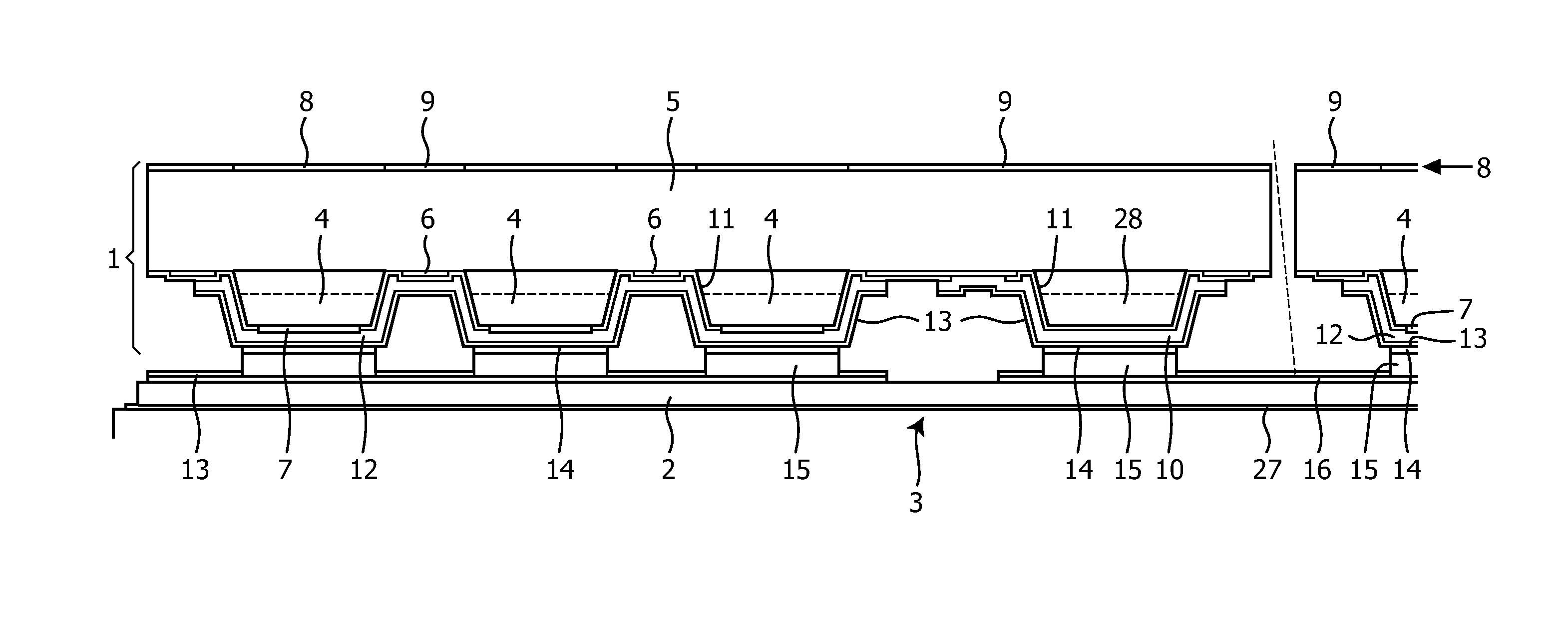
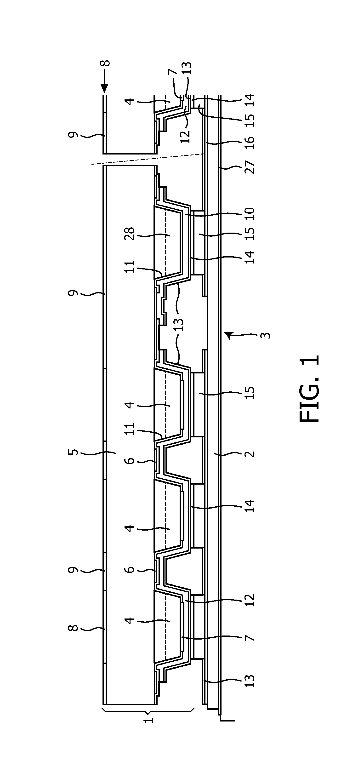
[0019]FIG. 1 shows an arrangement by which self alignment during soldering a bottom-emitter VCSEL chip 1 to a sub-mount 2 is achieved such that the emission windows of the VCSEL's of all chips on one sub-mount 2 are arranged in a desired exact manner with respect to each other. Each chip 1 comprises a VCSEL array of several VCSEL's from which three are shown with their p-type mesas 4 in FIG. 1. The figure shows the cross-section of one complete VCSEL chip 1 and only a small portion of a second chip at the right hand side. The VCSEL chips 1 comprise a n-type substrate 5 on which the p-type mesas 4 are formed in a known manner. The VCSEL's are connected by n-contacts 6 at the substrate side and p-contacts 7 on top of the mesas 4. The n-contacts 6 are metal layers having a low Ohmic contact (low Schottky barrier) to the n-type GaAs material of the substrate 5 or to the n-type DBR mirrors in case that mesa etching has stopped in these mirror layers (not shown in the figures). On the bot...


PUM


Abstract

The present invention relates to a method of assembling VCSEL chips (1) on a sub-mount (2). A de-wetting layer (13) is deposited on a connecting side of the VCSEL chips (1) which is to be connected to the sub-mount (2). A further de-wetting layer (13) is deposited on a connecting side of the sub-mount (2) which is to be connected to the VCSEL chips (1). The de-wetting layers (13) are deposited with a patterned design or are patterned after depositing to define connecting areas (21) on the sub-mount (2) and the VCSEL chips (1). A solder (15) is applied to the connecting areas (21) of at least one of the two connecting sides. The VCSEL chips (1) are placed on the sub-mount (2) and soldered to the sub-mount (2) to electrically and mechanically connect the VCSEL chips (1) and the sub-mount (2). With the proposed method a high alignment accuracy of the VCSEL chips (1) on the sub-mount (2) is achieved without time consuming measures.

Description

FIELD OF THE INVENTION[0001]The present invention relates to a method of assembling VCSEL chips (VCSEL: Vertical Cavity Surface Emitting Laser), in particular containing two-dimensional arrays of lasing emitters, on a sub-mount, in which the connection between the chips and the sub-mount is achieved by soldering.BACKGROUND OF THE INVENTION[0002]VCSEL IR power arrays allow tailored heating of a work piece by offering a tailored illumination pattern through a proper arrangement of the array. In specific applications e.g. when trying to create a very homogeneous illumination by projecting a superposition of magnified near-field images, a very accurate alignment (<5-10 μm) of the emission windows of the VCSEL chips with respect to each other is required. It is known that this high alignment accuracy when assembling the VSEL chips on a sub-mount can be achieved by performing active optical alignment. In this active optical alignment the lasers are activated and the emission is monitor...

Claims


Application Information

Patent Timeline
Patent Type & Authority Patents(United States)
IPC IPC(8): H01S5/022H01S5/42H01S5/30H01S5/028H01S5/024H01L23/00H01S5/023
CPCH01S5/02236H01L24/04H01L24/05H01S5/02272H01S5/423H01S5/02469H01S5/028H01S5/3013H01L2924/12032H01L2924/15788H01L2924/12042H01S5/0237H01S5/0233H01S5/023H01L2924/00H01S5/022H01S5/0235
Inventor PRUIJMBOOM, ARMANDDUMOULIN, RAIMOND LOUISMILLER, MICHAEL
Owner TRUMPF PHOTONIC COMPONENTS GMBH
Why Eureka
Try Eureka