Autoclavable vacuum lifter

a vacuum lifter and autoclave technology, applied in the field of autoclavable vacuum lifters, can solve the problems of vacuum lifters having aluminum parts, vacuum lifters that do not hold up well to the standard disinfection/autoclave protocols, aluminum oxidation readily,

a vacuum lifter and autoclave technology, applied in the field of autoclavable vacuum lifters, can solve the problems of vacuum lifters having aluminum parts, vacuum lifters that do not hold up well to the standard disinfection/autoclave protocols, aluminum oxidation readily,

US20060226666A1Inactive Publication Date: 2006-10-12CHAVDA KISHOR N +1

Image

  • Autoclavable vacuum lifter
  • Autoclavable vacuum lifter
  • Autoclavable vacuum lifter

Examples


Embodiment Construction

[0023] The present invention is more particularly described in the following examples that are intended as illustrative only since numerous modifications and variations therein will be apparent to those skilled in the art. As used in the specification and in the claims, โ€œaโ€, โ€œan,โ€ and โ€œtheโ€ can mean one or more, depending upon the context in which it is used. The preferred embodiment is described with reference to the figures, in which like numbers indicate like parts throughout the figures.

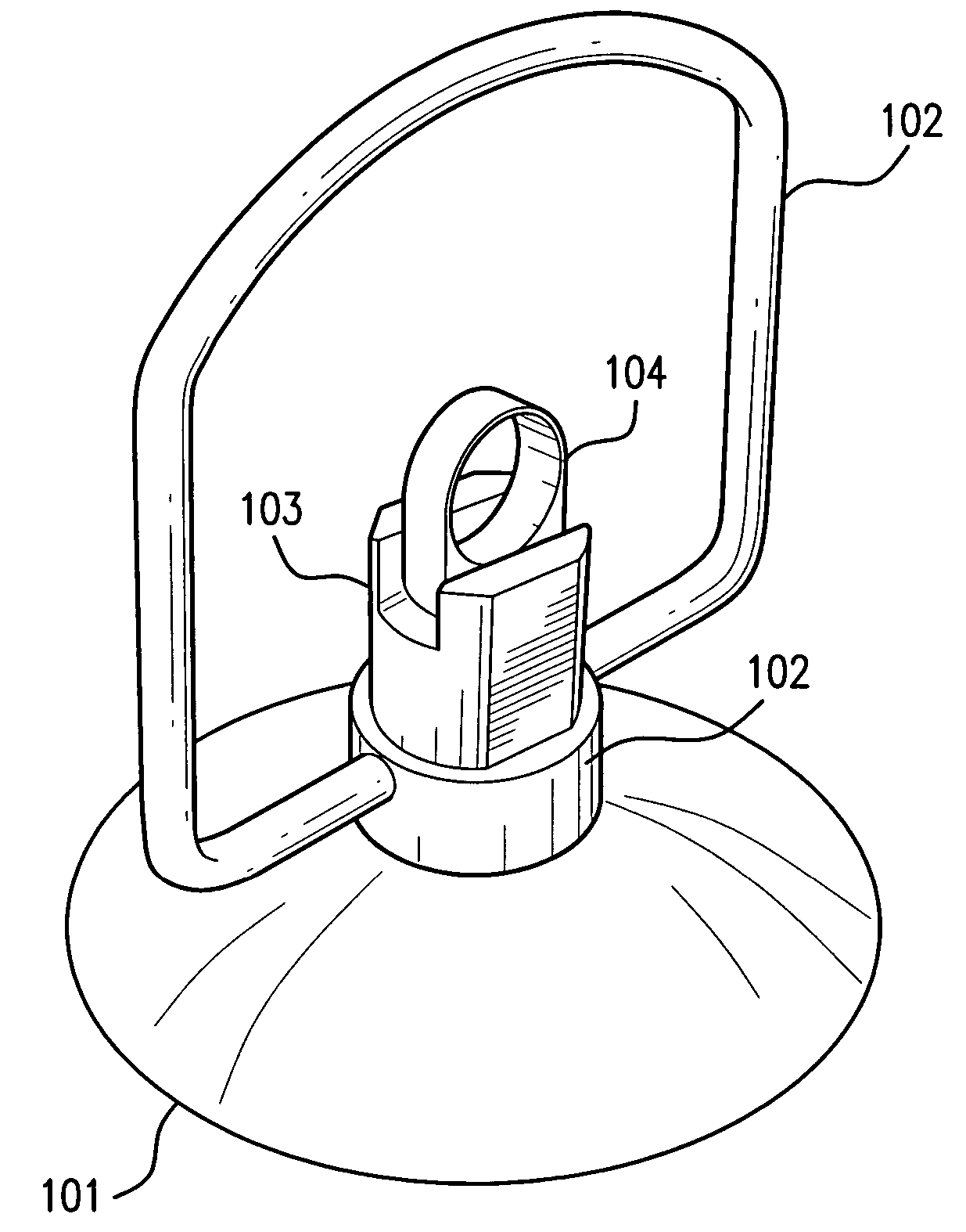
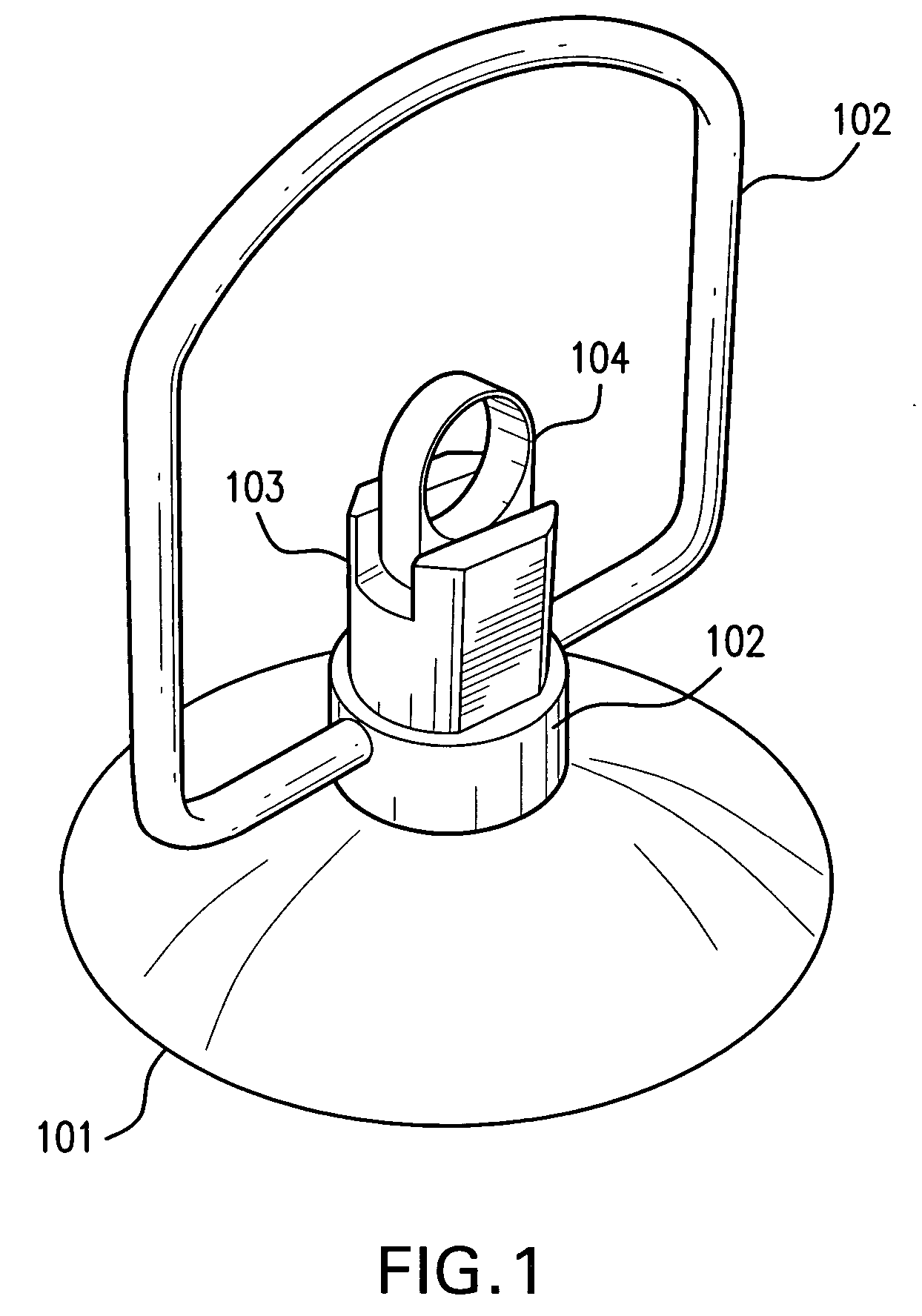
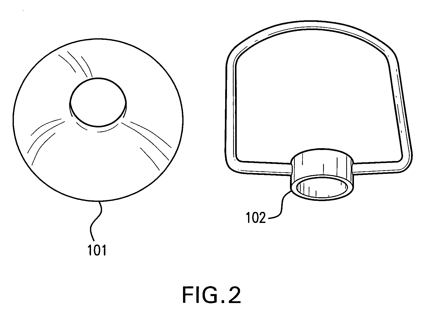
[0024] The various elements of the vacuum lifter of the present invention are depicted in FIGS. 1 through 5. A resilient suction cup (101), which is made from materials, such as for example, silicon, which can withstand high temperatures and be strong enough to support the objects to be transported can be employed. The suction cup has a bleed hole (404) in the hub (405). A threaded center piece (301) is tightly fitted inside the bleed hole (404) of the hub (405). The threaded center piece (301) ...


PUM


Abstract

The present invention relates to an apparatus that aids in the transportation of objects having at least one side with a smooth, flat surface. The vacuum lifter is autoclavable and washable by disinfectants routinely used to maintain aseptic compliance in industries such as the pharmaceutical and food industries. In addition the vacuum lifter of the present invention includes a check valve assembly that can be optionally maintained in the open position during the autoclave or disinfection operation.

Description

FIELD OF THE INVENTION [0001] The present invention relates to an apparatus that aids in the transportation of objects having at least one side with a smooth, flat surface. The vacuum lifter is autoclavable and washable by disinfectants routinely used in the pharmaceutical and food industries. BACKGROUND OF THE INVENTION [0002] Currently, commercially available suction (vacuum) lifters typically are constructed of a rubber suction cup affixed to an aluminum handle. The rubber suction-cup is placed on the smooth, flat, non-porous surface of the object to be transferred. Air is evacuated out of the suction cup and the edge of the vacuum cup forms a seal with the surface of the object. The ensuing vacuum grips the surface of the object and holds it, thus allowing the object to be lifted and transferred to a desired location. The vacuum is broken to release the suction lifter from the object. There are many models of suction lifters commercially available such as those offered by Allsta...

Claims


Application Information

Patent Timeline
12 Oct 2006
Publication
US20060226666A1
IPC
B25J15/06
CPC
B25B11/007; B65G2207/26; B65G47/91
Inventors
CHAVDA, KISHOR N.; GOOD, RANDY LEE