Wear detection by transponder destruction

a technology of transponder and wear detection, applied in the field of wear detection by transponder destruction, to achieve the effect of increasing wear resistance, particular wear resistance or hardness

Inactive Publication Date: 2006-10-12
MERI ENTSORGUNGSTECHN FUR DIE PAPIERIND
View PDF5 Cites 30 Cited by
  • Summary
  • Abstract
  • Description
  • Claims
  • Application Information

AI Technical Summary

Benefits of technology

[0012] In this case, a depression which is open in the direction of the transmitting / receiving device is provided in the machine part for the transponder device, in which depression the transponder device is inserted. One such depression with a predetermined depth is preferably incorporated on the circumference of a rotating component. This depression, with the transponder device located in it, is advantageously filled with a suitable synthetic resin, which is heat-resistant and / or pressure-resistant, depending on the application. In order to further increase the wear resistance, the synthetic resin preferably has non-metallic filling particles added to it. Particular wear-resistance or hardness can be achieved by ceramic particles, which do not at the same time adversely affect, or scarcely adversely affect, the signal flow between the transmitting / receiving device and the transponder device.

Problems solved by technology

This transmission method is particularly suitable for use in metallic machine parts, since frequency-modulated transponder devices can produce erroneous signals owing to the metallic environment.

Method used


Image

  • Wear detection by transponder destruction
  • Wear detection by transponder destruction
  • Wear detection by transponder destruction

Examples


Embodiment Construction

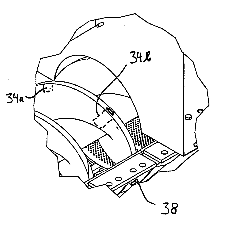
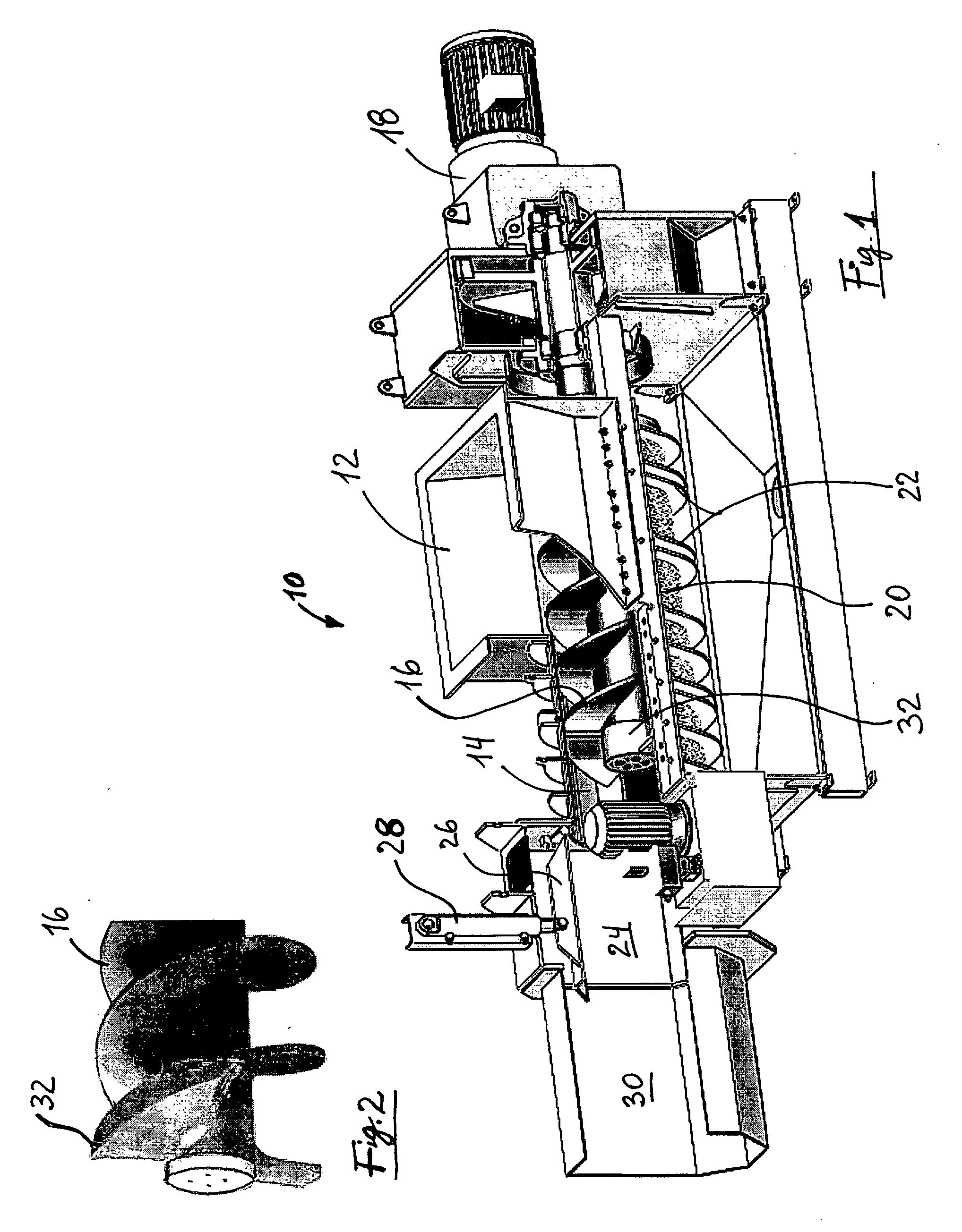
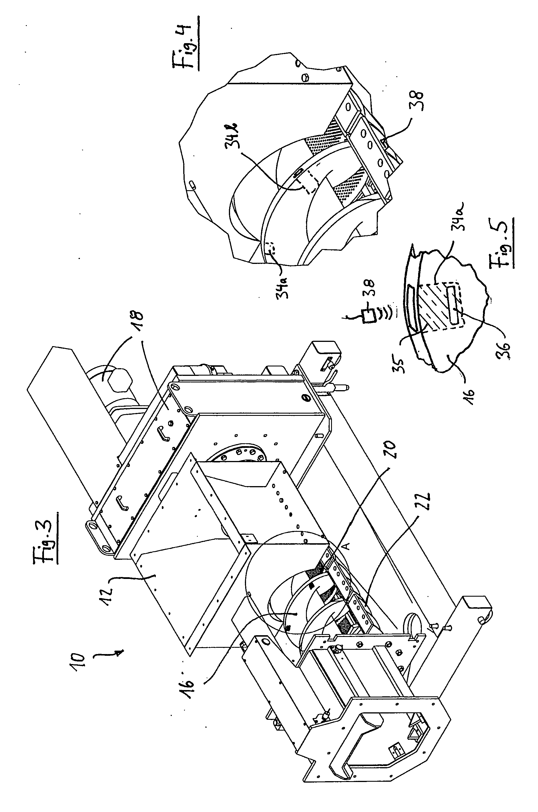
[0021]FIGS. 1 and 3 show the same machine, which is a residual material compression apparatus 10 (a so-called compactor) for disposal of residual material from sewage processing, in which the residual materials (so-called rejects), which have been separated by means of various separation methods, are compressed to a major extent with the aim of compacting them as much as possible. This residual material compression apparatus has an inlet 12 which communicates with a cylindrical compression area 14, in which a worm 16 is arranged, which is driven via a drive device 18 that is not illustrated in any more detail. The cylindrical wall 20 of the compression area 14 is provided with apertures for liquid to pass through during the pressing process, and with radial, annular reinforcing ribs 22.

[0022] A pressing zone 24 is provided in front of the axial free end of the worm 16 and surrounds at least one pressing plate 26 which can be operated via a hydraulic device 28. An outlet 30 for the ...


PUM


Abstract

The invention relates to a system and a method for the detection of the wear state of machine parts which are subject to mechanical wear, by means of an electronic transmitting / receiving device (38) and at least one transponder device (36), which is embedded in the machine part (16) and sends back an acknowledgement signal in response to a transmitted signal which is transmitted by the transmitting / receiving device (38), in which case the reaching of a predetermined wear value can be indicated by the destruction of the transponder device (36) and by the lack of the acknowledgement signal associated with this. The invention is based on the discovery that the arrangement of a transponder device at a specific position which is a measure of a predetermined wear state means that the operational readiness of the transponder device, on the one hand, is indicated in advance by its signal return, and the reaching of the predetermined wear value is indicated by its destruction.

Description

BACKGROUND OF THE INVENTION [0001] 1. Technical Field of the Invention [0002] The invention relates to a system for the detection of the wear state of machine parts which are subject to mechanical wear, by means of an electronic transmitting / receiving device and at least one transponder device which is embedded in the machine part and sends back an acknowledgement signal in response to a transmitted signal which is transmitted by the transmitting / receiving device. [0003] 2. Description of the Prior Art [0004] Many technical fields relating to heavy machine construction make use of machine parts which are subject to the influence of large forces during operation, and are thus continuously subject to high wear. By way of example, in the field of waste separation and reprocessing and mining machines, large feed or processing apparatuses such as drills or worm feeds are used, which are subject to relatively rapid wear, in which case the wear state and / or the reaching of a wear limit mus...

Claims


Application Information

Patent Timeline
Patent Type & Authority Applications(United States)
IPC IPC(8): G08B13/14
CPCB65G33/24B65G2207/48B65G43/02
Inventor MENKE, LUCAS
Owner MERI ENTSORGUNGSTECHN FUR DIE PAPIERIND
Why Eureka
Try Eureka