Remote control device

a remote control and control device technology, applied in the field of remote control devices, can solve the problems of poor maneuverability of the track pad, inability to solve the above-mentioned drawbacks, and inability to achieve good maneuverability, etc., and achieve the effect of convenient operation and more intuitiveness

Inactive Publication Date: 2006-10-12
CANON KK
View PDF17 Cites 15 Cited by
  • Summary
  • Abstract
  • Description
  • Claims
  • Application Information

AI Technical Summary

Benefits of technology

[0016] Another objet of the present invention is to provide a remote control device capable of attaining more intuitive and easier operations than in conventional remote control devices.

Problems solved by technology

However, since several pushing operations of the cursors are required before selecting the desired operation in the above-mentioned remote control device, a considerable time is required for selecting steps so that a good maneuverability can not be attained.
However, since the above-mentioned remote control device can not identify a currently connected set (an operational panel to be displayed) and a proper operational method and when shapes of the operational panel to be displayed and the track pad are different, there remain the following drawbacks to be solved.
c) When a numeric panel for selecting a TV channel and a full key board panel are spread on a track pad with the same size, moving speeds of keys on the respective operational panels corresponding to a moving speed of the finger are quite different, particularly the moving speed of the full key board panel is too fast to operate so that a maneuverability of the track pad is poor.
Although Japanese laid open patent No. 10-11288 proposes a remote control method utilizing the track pad, it is not such an invention capable of solving the above-mentioned drawbacks.

Method used


Image

  • Remote control device
  • Remote control device
  • Remote control device

Examples


embodiment 1

[0061] Hereinafter embodiment 1 by the present invention is explained as referring to drawings.

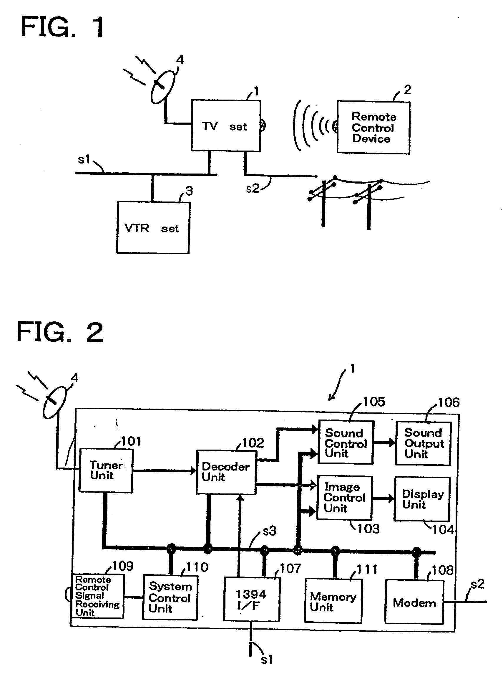
[0062]FIG. 1 is the block diagram showing the whole operational control system in embodiment 1.

[0063] A reference numeral “1” is a TV set for receiving TV broadcast, for transmitting / receiving remote control signals and data to / from device sets connected to the network and for controlling the connected device sets and the like. Further the TV set 1 displays received TV image data, images of device sets, various icons, control information and the like.

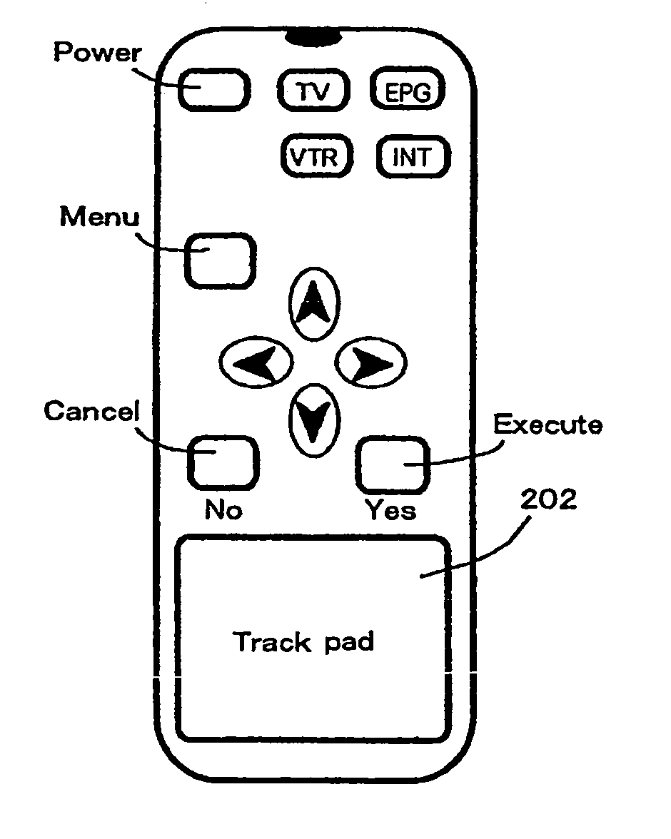
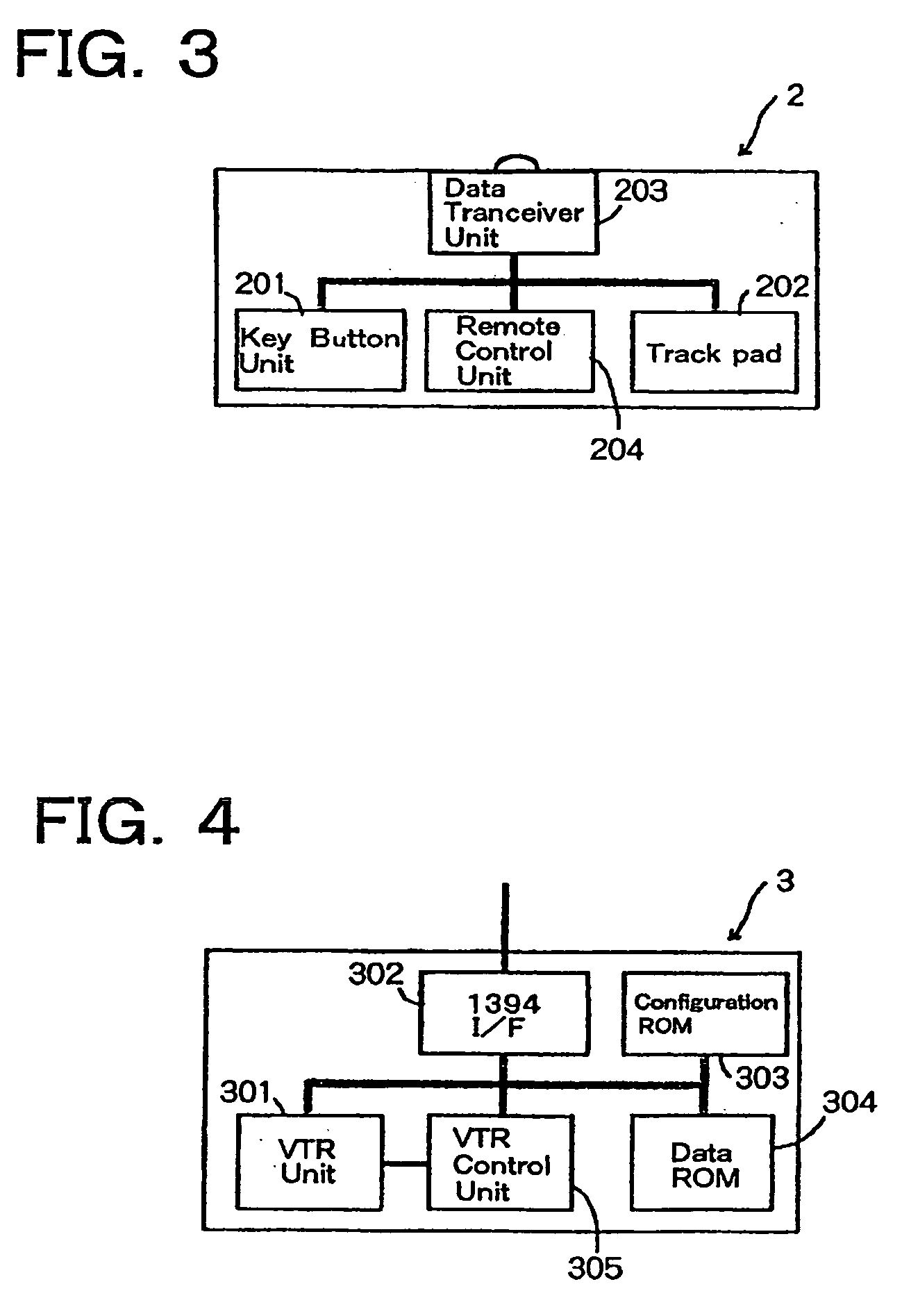
[0064] A reference numeral “2” is a remote control device for controlling and operating the TV set 1, a VTR set 3 and the like by a TV viewer. The VTR set 3 records and replays TV programs and other video and audio data.

[0065] The VTR set 3 can record and read out device information data for operating the VTR set 3 and these data can be inputted and outputted via a TV receiver arranged in the VTR set 3 and a network s1 which will be explai...

embodiment 2

[0194] In the present embodiment, an operational area of the track pad shown in FIG. 20F, which is not similar to the shape of the track pad as in embodiment 1 and is not rectangular in its shape, is explained.

[0195] As described in Embodiment 1, when a rectangular operational panel is related to the track pad, the finger is not moved out of the operational area, even if the finger is moved to positions at ends as shown in FIGS. 17N and Q. When the operational panel formed as shown in FIG. 20F is activated, a relational table between the operational panel and the track pad corresponding to a track pad allocation map shown in FIG. 20F is generated.

[0196] When a position G on the track pad is touched, the relational table between the operational table and the track pad is changed to a new table corresponding to a track pad allocation shown in FIG. 20G.

[0197] When the finger is moved from position G to position H as shown in FIG. 20H, the finger is moved out of the operational area ...

embodiment 3

[0198] As explained in the case of the VTR operational panel in embodiment 1, when the operational panel is not similar to the track pad, the relational table between the operational panel and the track pad is generated and changed in accordance with moved positions of the finger so as to keep the similarity between the operational panel and the operational area of the track pad. However, the operational area of the track pad may be fixed by the system control unit 110 beforehand.

[0199] The case of the fixed operational area of the track pad is explained as referring to FIGS. 22 and 23.

[0200] When the system control unit 110 detects the VTR operational panel is activated as shown in FIG. 22, based on the operational panel data the system control unit allocates the track pad as shown in FIG. 23U as keeping the similarity between the operational panel the operational area of the track pad. The allocated area of the track pad is divided into upper part and lower part, the lower part ...


PUM


Abstract

The present invention provides a remote control device having a track pad unit, an operational panel for remote-controlling an electronics device and a control means for controlling the operational panel in accordance with position data acquired by the track pad unit.

Description

BACKGROUND OF THE INVENTION [0001] 1. Field of the Invention [0002] The present invention relates to a remote control device which utilizes a track pad as one of the pointing devices. [0003] 2. Brief Description of the Related Art [0004] Remote control operations by a remote control device shown in FIG. 41 have been widely performed, when electronic apparatuses equipped with display devices such as a TV set and the like are operated by utilizing the remote control device. [0005] Recently a system in which a TV set, a VTR set, a stereophonic set and the like are mutually connected via a network interface prescribed by IEEE1394 and they are controlled by a remote control system equipped in the TV set, is proposed. In the above-mentioned system, operating panels of other sets not equipped with display units, are displayed on a display unit of the TV set. [0006] In the above-mentioned system it is necessary to control operations of a plurality of sets by one remote control device attach...

Claims


Application Information

Patent Timeline
Patent Type & Authority Applications(United States)
IPC IPC(8): G08C19/12H04L17/02G06F13/00G08C17/00H04B1/20H04N5/00H04Q9/00
CPCG06F3/0236G06F3/0485G06F3/04886G08C17/00H04B1/202H04N5/4403H04N21/42226H04N5/44582H04N2005/4419H04N2005/443H04N2005/4435H04N21/42224H04N5/44543H04N21/42204H04N21/42214H04N21/47
Inventor SHIBAMIYA, YOSHIKAZUYAMAMOTO, TAKASHIKUTSUNA, MASAKIFUKUDA, TETSU
Owner CANON KK
Why Eureka
Try Eureka