Projection optical unit and projection type video display device using the unit

a technology of projection optical unit and projection type, applied in the direction of optics, projectors, instruments, etc., can solve the problems of difficult to enlarge the field angle, the device cannot be thinning,

Active Publication Date: 2006-10-12
MAXELL HLDG LTD
View PDF9 Cites 53 Cited by
  • Summary
  • Abstract
  • Description
  • Claims
  • Application Information

AI Technical Summary

Benefits of technology

[0011] The present invention has been developed in view of such problems, and there is provided a preferable technology for constituting a rear projection type display device to be compact.
[0014] As described above, according to the present invention, it is possible to realize a compact device whose optical depth is small and in which a height of a lower part of a screen is small.

Problems solved by technology

Since the afocal converter disclosed in Patent Document 1 has a small magnification, it is difficult to enlarge a field angle, and thinning of the device cannot be achieved.
Even in the projection optical unit described in Patent Document 2, it is difficult to enlarge the field angle to such an extent that a rear projection type color video display device can be sufficiently thinned.
There is also a problem that it is difficult to manufacture the unit because lenses for use need to be individually eccentric.
Therefore, there is a problem that it is difficult to secure a positional precision of each lens at a manufacturing time, and it is difficult to manufacture the unit.
Since an eccentricity for correcting the trapezoidal distortion needs to be enlarged more, it becomes more difficult to manufacture the unit.
Accordingly, since a lens diameter becomes larger, it is difficult to reduce the depth of the conventional optical system more.

Method used


Image

  • Projection optical unit and projection type video display device using the unit
  • Projection optical unit and projection type video display device using the unit
  • Projection optical unit and projection type video display device using the unit

Examples


example 1

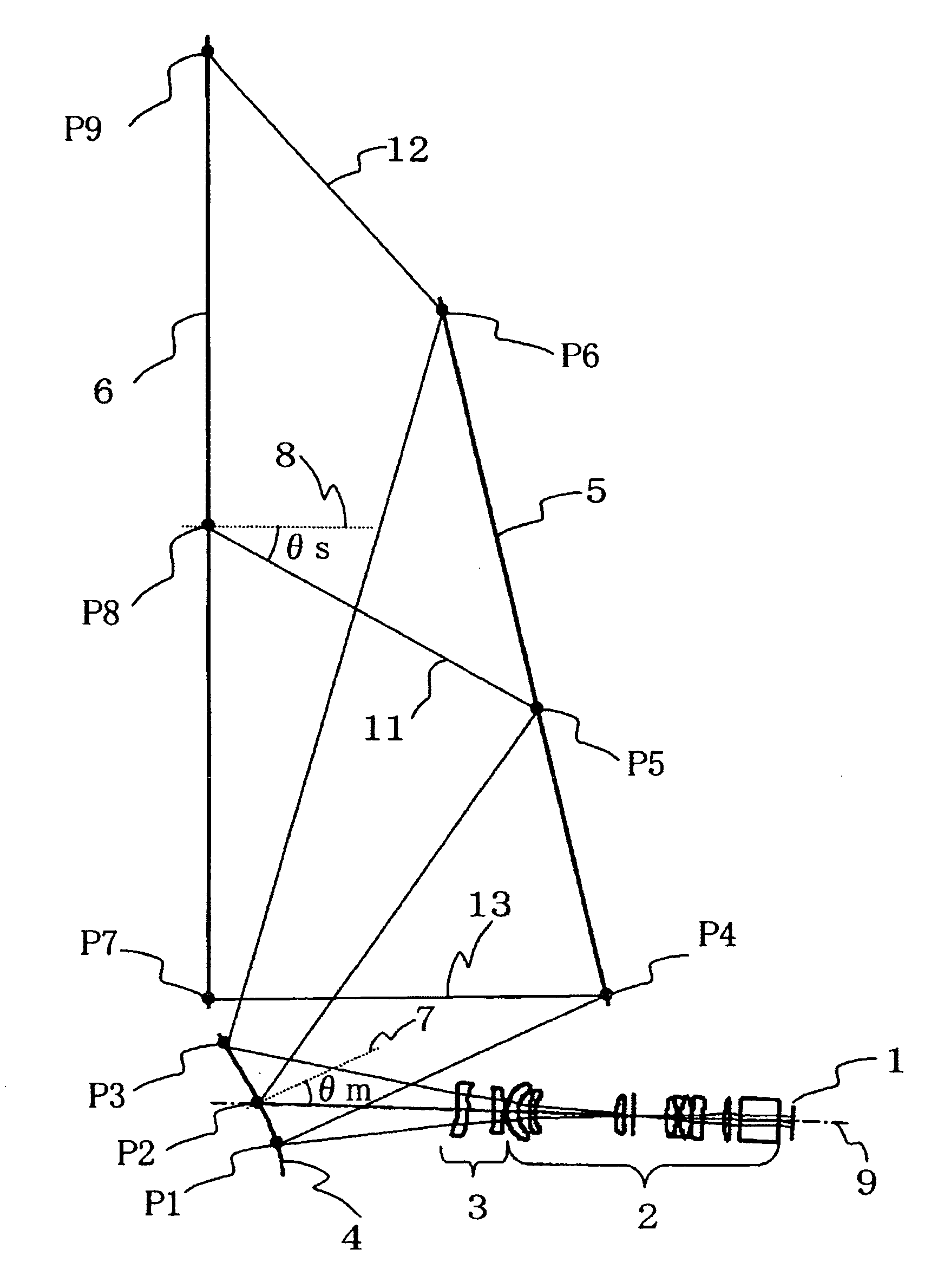
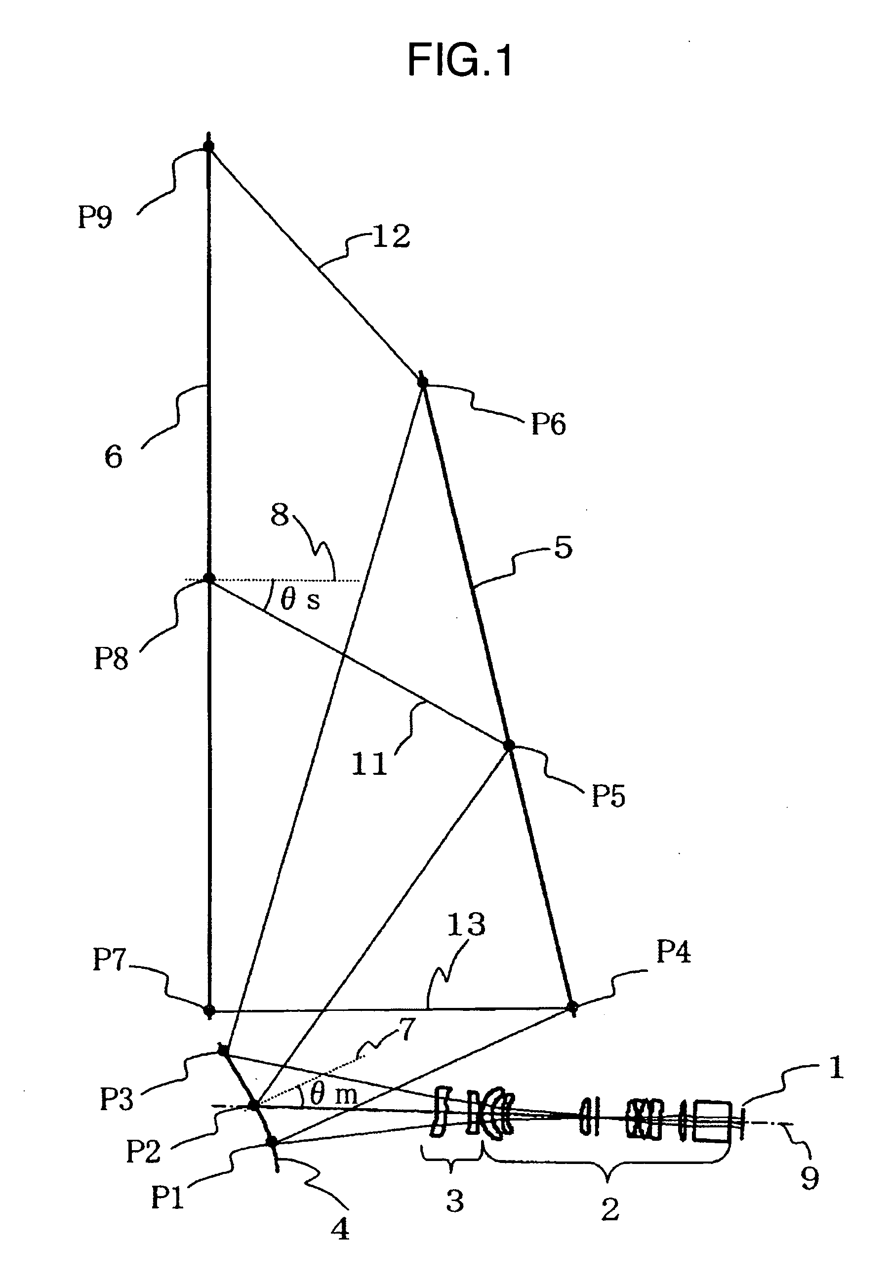
[0060] One typical example of the present embodiment using typical numerical values will be described with reference to FIGS. 4 to 7 and Tables 1 to 4. FIGS. 4 and 5 show ray diagrams of an optical system according to the present invention based on a first numerical value example, In the above-described XYZ orthogonal coordinate system, FIG. 4 shows a structure in a YZ section, and FIG. 5 shows that in an XZ section. FIG. 1 shows an example in which a folding mirror is disposed midway in a front group 12 of a projection lens 2, and an optical path is once bent in an X-axis direction. FIG. 4 omits this folding mirror, and shows an optical system developed in a Z-axis direction. FIG. 5 shows an optical system including the folding mirror to bend the optical path. A position or angle for disposing the folding mirror is somewhat arbitrary, and a function of each optical element is not influenced. Therefore, in the following description, the folding mirror is omitted.

[0061] In the prese...

example 2

[0079] Next, a second example will be described.

[0080] A second typical example of a projection optical unit according to the present invention will be described with reference to FIGS. 8 to 10 and Tables 5 to 8.

[0081]FIG. 8 shows a ray diagram of a second numerical value example of the present invention. Light emitted from an image display element 61 displayed on a lower side of FIG. 8 first passes, in order, through a front group 62 of a first optical system including transmission type lenses having rotationally symmetrical surface shapes, and a rear group 63 of the first optical system including transmission type lenses having free shaped surfaces. Thereafter, the light is reflected by a reflection surface 64 having a free shaped surface of a second optical system, and reflected by a flat rear mirror 65 before entering a screen 66.

[0082] Here, the front group 62 of the first optical system includes a plurality of refraction surfaces which are all rotationally symmetrical, four...

example 3

[0096] A third numerical value example according to the present invention will be described with reference to FIGS. 11 to 13 and Tables 9 to 12.

[0097]FIG. 11 shows a ray diagram of a third numerical value example of the present invention. Light emitted from an image display element 71 displayed on a lower side of FIG. 11 first passes, in order, through a front group 72 of a first optical system including transmission type lenses having rotationally symmetrical surface shapes, and a rear group 73 of the first optical system including transmission type lenses having free shaped surfaces. Thereafter, the light is reflected by a reflection surface 74 having a free shaped surface of a second optical system, and reflected by a flat rear mirror 75 before entering a screen 76. Here, the front group 72 of the first optical system includes refraction surfaces which are all rotationally symmetrical, four of the respective refraction surfaces are rotationally symmetrical non-spherical surfaces...


PUM


Abstract

In the image display device, a projection lens including a plurality of lenses for enlarging an image from an image display element is constituted of a front group and a rear group. The rear group includes at least one free-shaped-surface lens including a surface having a rotationally asymmetrical shape. Furthermore, the device includes at least one free-shaped-surface mirror having a rotationally asymmetrical reflection surface. Accordingly, a set can be formed to be compact while correcting trapezoidal distortion and aberration.

Description

INCORPORATION BY REFERENCE [0001] The present application claims priority from Japanese application JP2005-111517 filed on Apr. 8, 2005, the content of which is hereby incorporated by reference into this application. BACKGROUND OF THE INVENTION [0002] 1. Field of the Invention [0003] The present invention relates to a projection type video display device which projects an enlarged image on a screen to display an image, and a projection optical unit. [0004] 2. Description of the Related Art [0005] In a color video display device which enlarges and projects an image of a video display element on a screen by means of a projection optical unit, it is demanded that a depth of the device be reduced while obtaining an enlarged video having a sufficient size on the screen. To realize this, as described in, for example, JP-A-5-134213 (Patent Document 1), JP-A-2000-162544 (Patent Document 2), and JP-A-2002-357768 (Patent Document 3), there is known a projection optical unit having such a cons...

Claims


Application Information

Patent Timeline
Patent Type & Authority Applications(United States)
IPC IPC(8): G03B21/28
CPCG02B13/16G03B21/10G02B27/0025
Inventor HISADA, TAKANORIYOSHIKAWA, HIROKIOHISHI, TETSUYATSU, MASAHIKOHIRATA, KOJI
Owner MAXELL HLDG LTD
Why Eureka
Try Eureka