Heat-dissipating module of electronic device

a technology of heat dissipation module and electronic device, which is applied in the direction of electrical apparatus construction details, electrical apparatus casings/cabinets/drawers, instruments, etc., can solve the problems of increasing the internal temperature increasing the integration of electronic components and the watt consumption of the power supply, and increasing the temperature of the whole power supply. , to achieve the effect of increasing the heat dissipation efficiency of the power supply

Inactive Publication Date: 2006-10-12
DELTA ELECTRONICS INC
View PDF12 Cites 60 Cited by
  • Summary
  • Abstract
  • Description
  • Claims
  • Application Information

AI Technical Summary

Benefits of technology

[0006] An object of the present invention is to provide a heat-dissipating module of a power supply which comprises a heat-conducting interface disposed between the power supply and the system cooling device and served as an auxiliary heat-dissipating device of the power supply, so that partial heat generated by the power supply can be dissipated via the system cooling device to further increase the heat-dissipating efficiency of the power supply.

Problems solved by technology

As known, when the power supply is operating, the electronic components included in the power supply will generate heat, which results in the increase of internal temperature of the power supply.
However, along with the technology development of the electronic products and in response to the requirements of the users, more and more electronic components are loaded on the printed circuit board (PCB) inside the power supply, resulting in the increases of the integration of the electronic components and the watt consumption of the power supply.
Since the watt consumption increases, it is inevitable to increase the temperature of the whole power supply.
Therefore, how to improve the heat-dissipating efficiency of the power supply is an important issue.

Method used


Image

  • Heat-dissipating module of electronic device
  • Heat-dissipating module of electronic device
  • Heat-dissipating module of electronic device

Examples


Embodiment Construction

[0024] The present invention will now be described more specifically with reference to the following embodiments. It is to be noted that the following descriptions of preferred embodiments of this invention are presented herein for purpose of illustration and description only; it is not intended to be exhaustive or to be limited to the precise form disclosed.

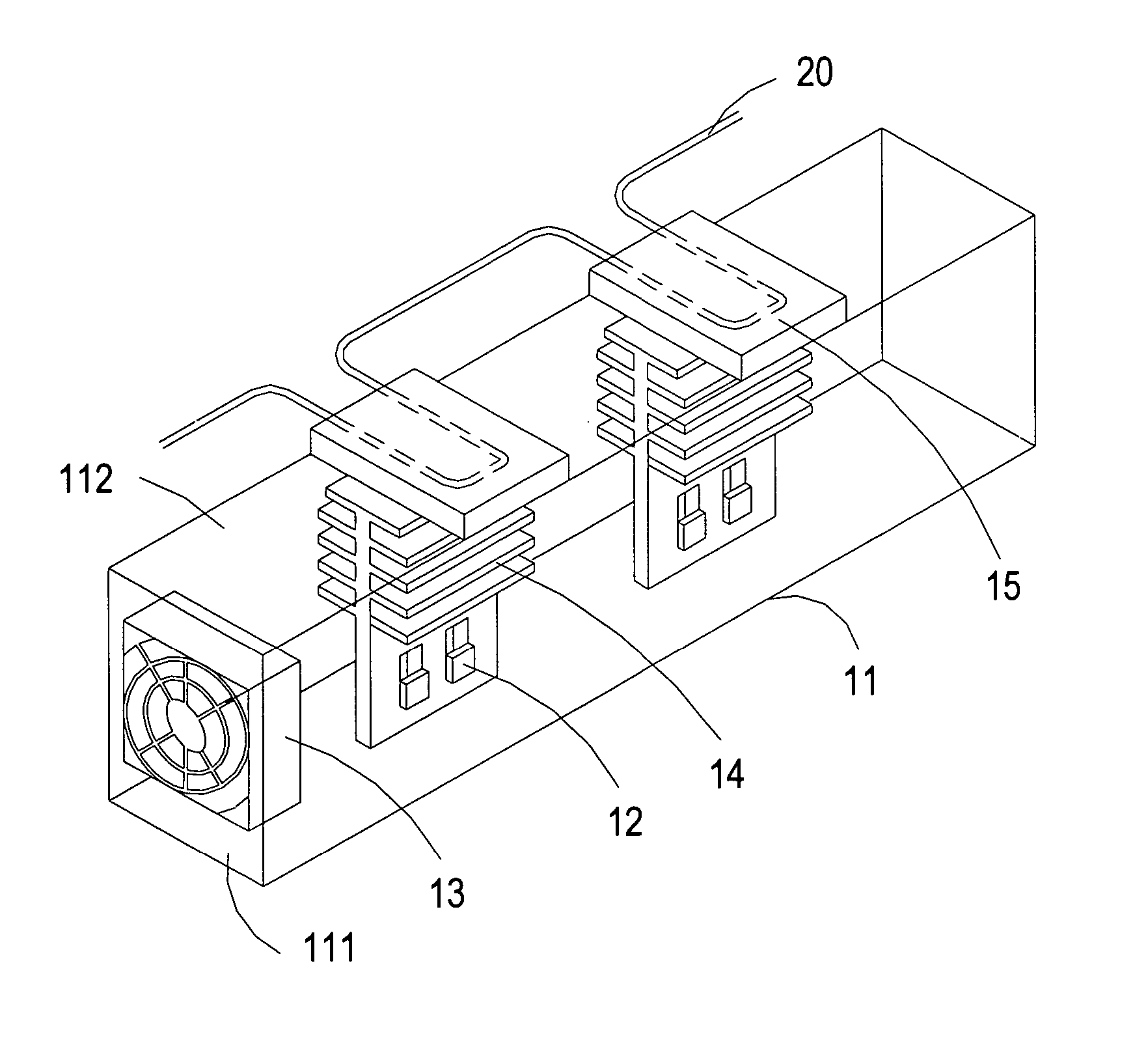
[0025] The present invention relates to a heat-dissipating module of an electronic device. The present techniques are illustrated with the following embodiments for a power supply, but the electronic device that is applicable to the present techniques is not limited to the power supply. Any electronic device that is applicable to the following techniques is incorporated herein for reference.

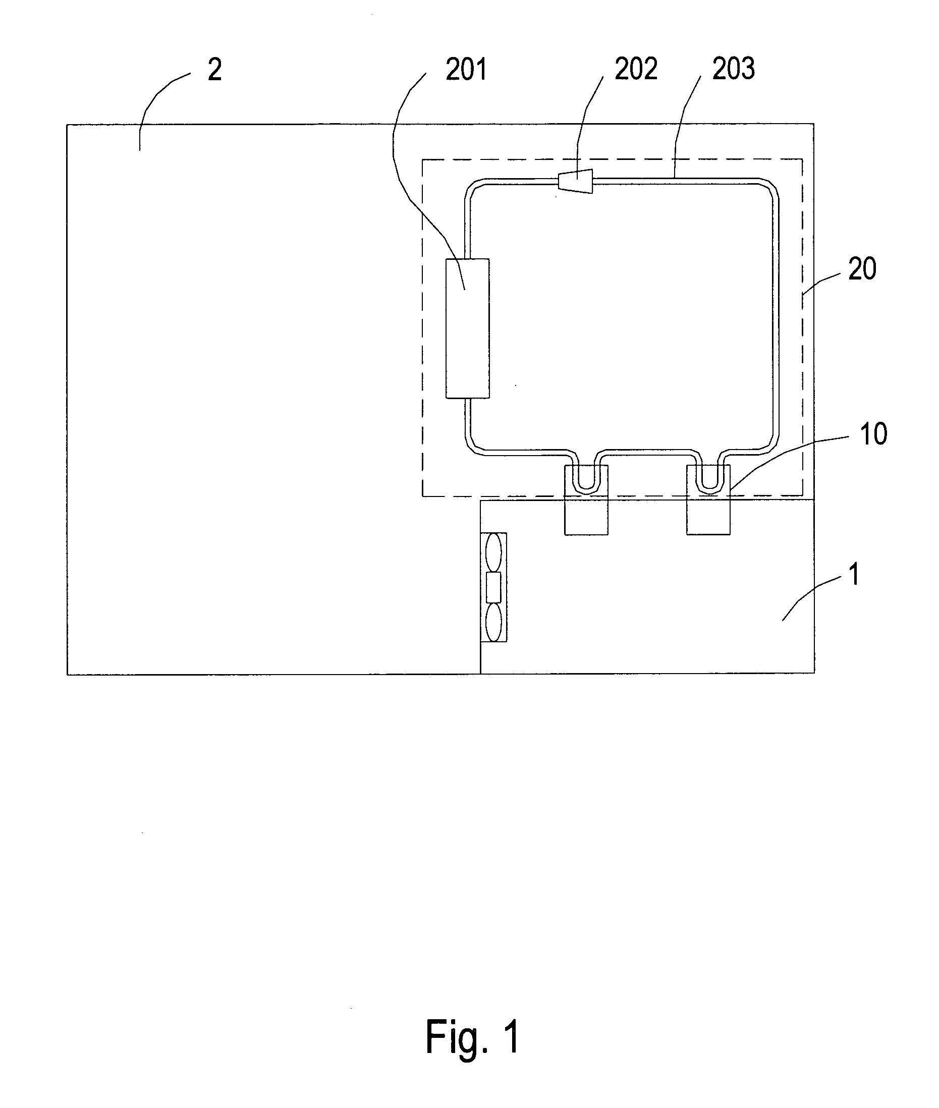
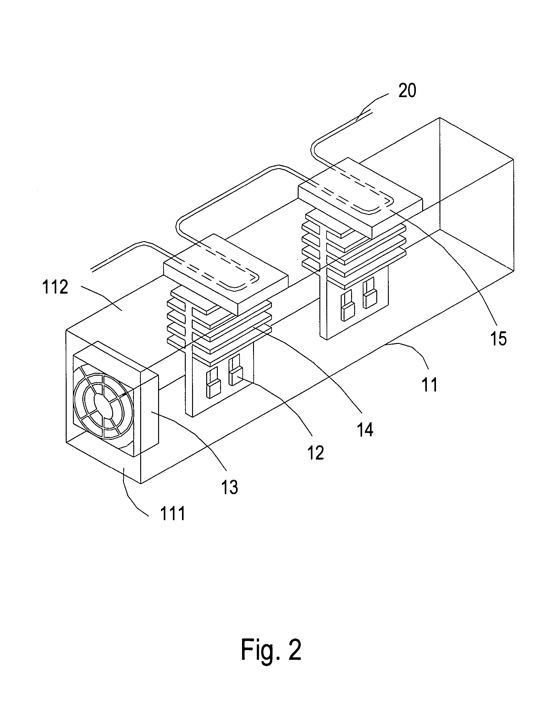
[0026] Please refer to FIG. 1, which is a schematic diagram showing the disposition of the present electronic device and the system cooling device. As shown in FIG. 1, the electronic device is a power supply 1, which is disposed in the syst...


PUM


Abstract

The heat-dissipating module of the electronic device comprises a fan, a first heat-dissipating component and a second heat-dissipating component. The fan is disposed on a first side of the casing, and the first heat-dissipating component is disposed on a second side of the casing and in heat contact with the electronic components for transferring heat generated by the electronic components to the casing. The second heat-dissipating component is disposed on an outer sidewall of the casing corresponding to the first heat-dissipating component and in heat contact with a system cooling system. Thereby, the heat generated by the electronic components is transferred to the second heat-dissipating component through the first heat-dissipating component and the casing, and then dissipated by the system cooling device.

Description

FIELD OF THE INVENTION [0001] The present invention relates to a heat-dissipating module of an electronic device, and more particularly to a heat-dissipating module of a power supply. BACKGROUND OF THE INVENTION [0002] Power supply is an essential device for various electric appliances or information products. As known, when the power supply is operating, the electronic components included in the power supply will generate heat, which results in the increase of internal temperature of the power supply. Generally, there is one or plural heat-dissipating fans disposed on the casing of the power supply for quickly blowing the internal hot air out of the casing or introducing the external cold air into the casing for cooling down the power supply. Hence, the temperature inside the casing is decreased for preventing the electronic components from breakdown or the lifespan thereof from being shortened due to the over-temperature condition. [0003] However, along with the technology develop...

Claims


Application Information

Patent Timeline
Patent Type & Authority Applications(United States)
IPC IPC(8): H05K7/20
CPCH01L23/467H01L23/473H05K7/20909H05K7/20927H01L2924/0002H01L2924/00
Inventor CHEN, YIN-YUANCHANG, REN-CHUNYU, CHEN-YU
Owner DELTA ELECTRONICS INC
Why Eureka
Try Eureka