Pintle injector

Inactive Publication Date: 2006-10-19
JAPAN AEROSPACE EXPLORATION AGENCY
View PDF8 Cites 9 Cited by
  • Summary
  • Abstract
  • Description
  • Claims
  • Application Information

AI Technical Summary

Benefits of technology

[0026] According to the pintle injector of the present invention, the first injector flow path of the first pintle injector port is formed as a regenerative cooling path. Therefore, the propellant can obtain the gasification heat equivalent to the latent heat and sensible heat from the combustion chamber, to become a high temperature gas and be injected from the first injection port. As a result, high temperature propellant gas is injected from the first pintle injector port. On the other hand, comparatively low temperature liquid or gas propellant is injected from the second pintle injector port. In this way, high temperature gas propellant and low temperature liquid or gas propellant, in other words the same or different type of propellant with differing temperatures, states, and properties are generated. The fuel and the oxidizer are mixed based upon these, so atomization and mixing of the fuel and oxidizer is promoted. In particular, when fuel and oxidizer are mixed such as high temperature propellant gas and low temperature liquid or gas propellant are impinging on either side of another propellant, propellant atomization and mixing is further promoted. Also, when the first pintle injector port and the second pintle injector port are formed as a row of annular orifice holes or annular slits, the propellants injected from both the first pintle injector port and the second pintle injector port are uniformly atomized and dispersed, so atomization and mixing of propellant is promoted.
[0027] Furthermore, a single or two or more types of propellant, either fuel or oxidizer, injected in the axial direction from an axial injector port, the same or a different propellant injected from the first pintle injector port i

Problems solved by technology

This could result in combustion vibrations, combustion spikes, or other abnormal combustion, and lowering of combustion efficiency.
However, in case of using the above pi

Method used


Image

  • Pintle injector
  • Pintle injector
  • Pintle injector

Examples


Example

Embodiment 1

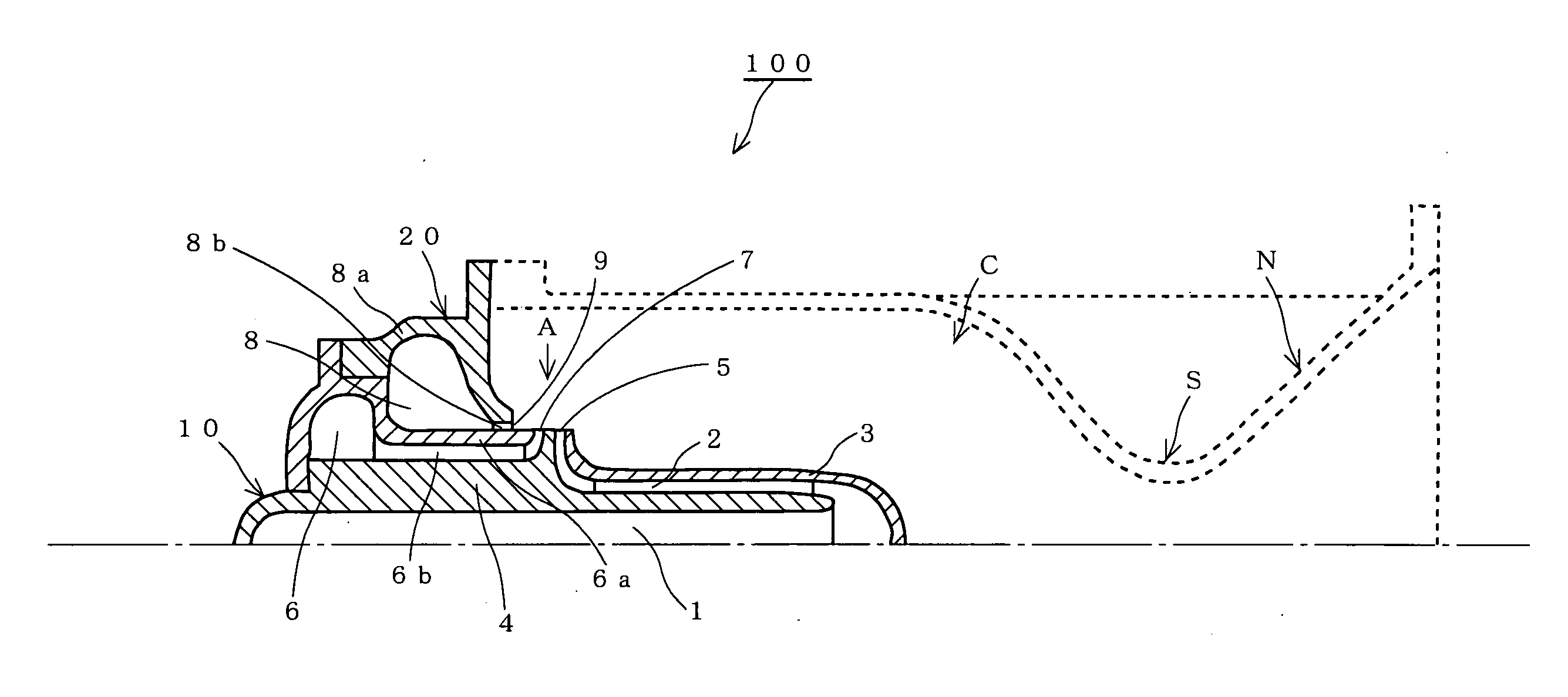
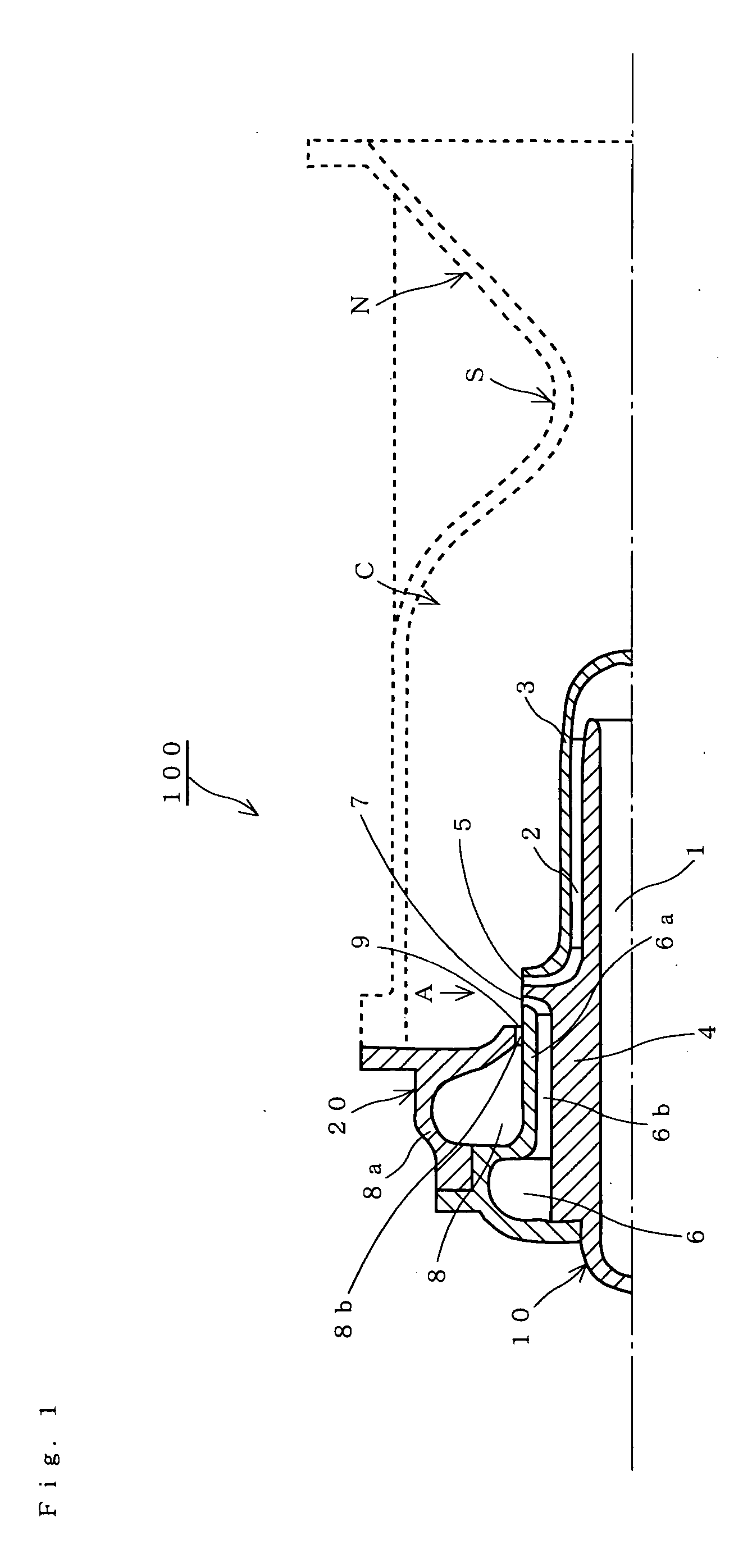
[0038]FIG. 1 is a cross-section showing a pintle injector 100 according to a first embodiment of the pintle injector of the present invention.

[0039] The pintle injector 100 includes a pintle injector part 10 and an axial injector part 20. The pintle injector part 10 includes a first propellant channel 1 that transmits fuel and a second propellant channel 6 that transmits oxidizer. The first propellant channel 1 projects into a combustion chamber C, and fuel is injected in the radial direction from a first pintle injector port 5. Oxidizer is injected from a second pintle injector port 7 in the radial direction. The axial injector part 20 includes a third propellant channel 8 that transmits fuel, and fuel is injected in the axial direction from an axial injector port 9.

[0040] Between a pintle external wall 3 and a pintle internal wall 4 of the pintle injector part 10, a plurality of first injector flow paths 2 is formed in a circle at equal intervals. Also, the shape of...

Example

Embodiment 2

[0046]FIG. 3 is a cross-section showing a pintle injector 200 according to a second embodiment of the present invention.

[0047] The pintle injector 200 includes a pintle injector part 11 and an axial injector part 20. The pintle injector part 11 includes a first propellant channel 1 and a second propellant channel 6. The first propellant channel 1 projects into a combustion chamber C. Part of the oxidizer is injected from a first pintle injector port 5 in the radial direction, and the rest of the oxidizer is injected from a second pintle injector port 7 in the radial direction. The axial injector part 20 includes a third propellant channel 8 that transmits fuel, and injects fuel from an axial injector port 9 in the axial direction.

Example

[0048] In the pintle injector 100 of the first embodiment, part of the fuel exchanges heat with the pintle external wall 3 and is gasified into a high temperature fuel gas and injected from the first pintle injector port 5. Together with the comparatively low temperature liquid fuel injected from the axial injector port 9, the high temperature fuel gas impinges on the oxidizer injected from the second pintle injector port 7 so that the fuel and oxidizer are mixed. However, in this embodiment part of the oxidizer exchanges heat with a pintle external wall 3 and is gasified into a high temperature oxidizer gas and injected from the first pintle injector port 5. The rest of the oxidizer that is at a comparatively low temperature and is injected from the second pintle injector port 7, and together with the high temperature oxidizer gas injected from the first pintle injector port 5 mixes with the fuel injected from the axial injector port 9.

[0049] In the pintle injector part 11, part o...


PUM


Abstract

To provide a simple structured and low cost pintle injector capable of uniformly atomizing and mixing fuel and oxidizer, and further improving the combustion efficiency of the combustion reaction in the combustion chamber. A pintle injector part having a first propellant channel forms a first injector flow path as a regenerative cooling path along the pintle external wall that projects into a combustion chamber, and high temperature fuel gas is injected from the first pintle injector port. On the other hand, an axial injector part is located upstream of the first pintle injector port, and injects comparatively low temperature liquid or gas fuel from an axial injector port via a third propellant channel and a third injector flow path. Oxidizer is injected from a second pintle injector port via a second propellant channel and a second injector flow path, and is atomized and mixed while being impinged on either by the high temperature fuel gas and the comparatively low temperature liquid or gas fuel. The fuel injected from the first pintle injector port and the fuel injected from the axial injector port may be the same type or a different type of fuel.

Description

BACKGROUND OF THE INVENTION [0001] 1. Field of the Invention [0002] The present invention relates to a pintle injector, and more particularly to a pintle injector with a simple structure and low cost that uniformly atomizes and mixes fuel and oxidizer that can contribute to further improvements in the combustion efficiency of the combustion reaction in a combustion chamber. [0003] 2. Description of the Related Art [0004] Liquid rockets have a more complex structure compared with solid rockets. However, they have advantages such as suitability for large scale, thrust can be easily controlled, and so on. Therefore they are widely used in the main propulsion system of rockets for space transportation, or in the gas jet devices for orbiter maneuvering system or reaction control system of artificial satellites. [0005] Liquid rockets are classified according to the propellant into monopropellant propulsion systems and bipropellant propulsion systems. In monopropellant propulsion systems t...

Claims


Application Information

Patent Timeline
IPC IPC(8): F02K9/52
CPCF02K9/52F23R3/28F23D11/443F23D11/106
Inventor HASEGAWA, KEIICHIMORIYA, SHINICHI
Owner JAPAN AEROSPACE EXPLORATION AGENCY
Why Eureka
Try Eureka