Thread drive with monitored safety nut

a technology of safety nut and thread drive, which is applied in the direction of toothed gearings, belts/chains/gearrings, mechanical instruments, etc., can solve the problems of complex construction and achieve the effect of reducing the electrical connection

Inactive Publication Date: 2006-10-19
BOSCH REXROTH MECHATRONICS
View PDF8 Cites 2 Cited by
  • Summary
  • Abstract
  • Description
  • Claims
  • Application Information

AI Technical Summary

Benefits of technology

[0007] The contact portion of the safety nut can surround the entire safety nut or only a small portion of it. The first embodiment is simpler in construction, since the second embodiment is predominantly considered for use when already existing safety nut constructions are being upgraded. The contact portion of the safety nut may for instance be embodied as a thin disk, whose internal contour is embodied as equidistant from the surface of the threaded spindle.
[0008] For interrupting the electrical connection between the contact portion of the safety nut and the threaded spindle, the contact portion of the safety nut may be provided with an electrically insulating coating. The coating is preferably interrupted only in the contact region with the threaded spindle. The contact portion of the safety nut can therefore be secured without problems to such electrically conductive connection means as screws on the remaining safety nut, or on the load-bearing nut, without interrupting the electrical insulation.
[0010] It may also be provided that the load-bearing nut is embodied as a roller body circulation nut, and the electrical connection between the contact portion of the safety nut and the threaded spindle is interrupted by roller bodies of electrically nonconductive material, preferably ceramic balls. In a thread drive of the invention, the use of a roller body circulation nut is in principle advantageous, because it functions virtually without wear. It is thus assured that the gap between the safety nut and the threaded spindle is preserved over the entire service life. Using electrically nonconductive roller bodies means that the electrical connection between the nut body and the threaded spindle can easily be interrupted, since these two components do not otherwise touch. In addition, an electrically nonconductive lubricant for the roller bodies may be provided.
[0012] In the thread drive of the invention, an evaluation device may be provided, which is electrically connected to the contact portion of the safety nut and to the threaded spindle. An electrical voltage can be applied to these components, and the evaluation device monitors whether an electrical current is flowing, or not. If it is flowing, a signal is output that indicates that the thread drive has failed. Ground potential may applied to the threaded spindle, so that avoiding an unwanted flow of current does not require that the threaded spindle be complicatedly insulated electrically from the higher-order component unit.
[0013] Furthermore, the threaded spindle can be rotatably supported on at least one bearing, and the electrical connection between the evaluation device and the threaded spindle extends via the bearing. Typically in a thread drive, the threaded spindle is driven rotatably by a motor. For reducing an electrical connection between the threaded spindle and the evaluation device, a transmitter of rotation would thus have to be used. That function can easily be taken over by the bearing of the threaded spindle, especially whenever a radial roller bearing is used, since such a roller bearing is typically electrically conductive. Since in normal operation, namely in the first operating state, electrical current does not flow through the bearing, nor is a voltage applied between the inner and outer rings, there is no need to fear bearing damage.
[0014] In a refinement of the invention, it is proposed that the contact region between the contact portion of the safety nut and the threaded spindle is sealed off from the environment. For the functional safety of the monitoring, it is decisive that an electrical contact between the portion of the safety nut and the threaded spindle is not unintentionally made as a result of dirt particles, such as metal chips. This can be prevented by means of a seal. If a roller body circulation nut is used as the load-bearing nut, sealing it is necessary anyway. It is therefore advantageous if one seal is located on each of the two end regions of the load-bearing nut and safety nut combination.

Problems solved by technology

This construction has the disadvantage of being very complicated.

Method used


Image

  • Thread drive with monitored safety nut
  • Thread drive with monitored safety nut
  • Thread drive with monitored safety nut

Examples


Embodiment Construction

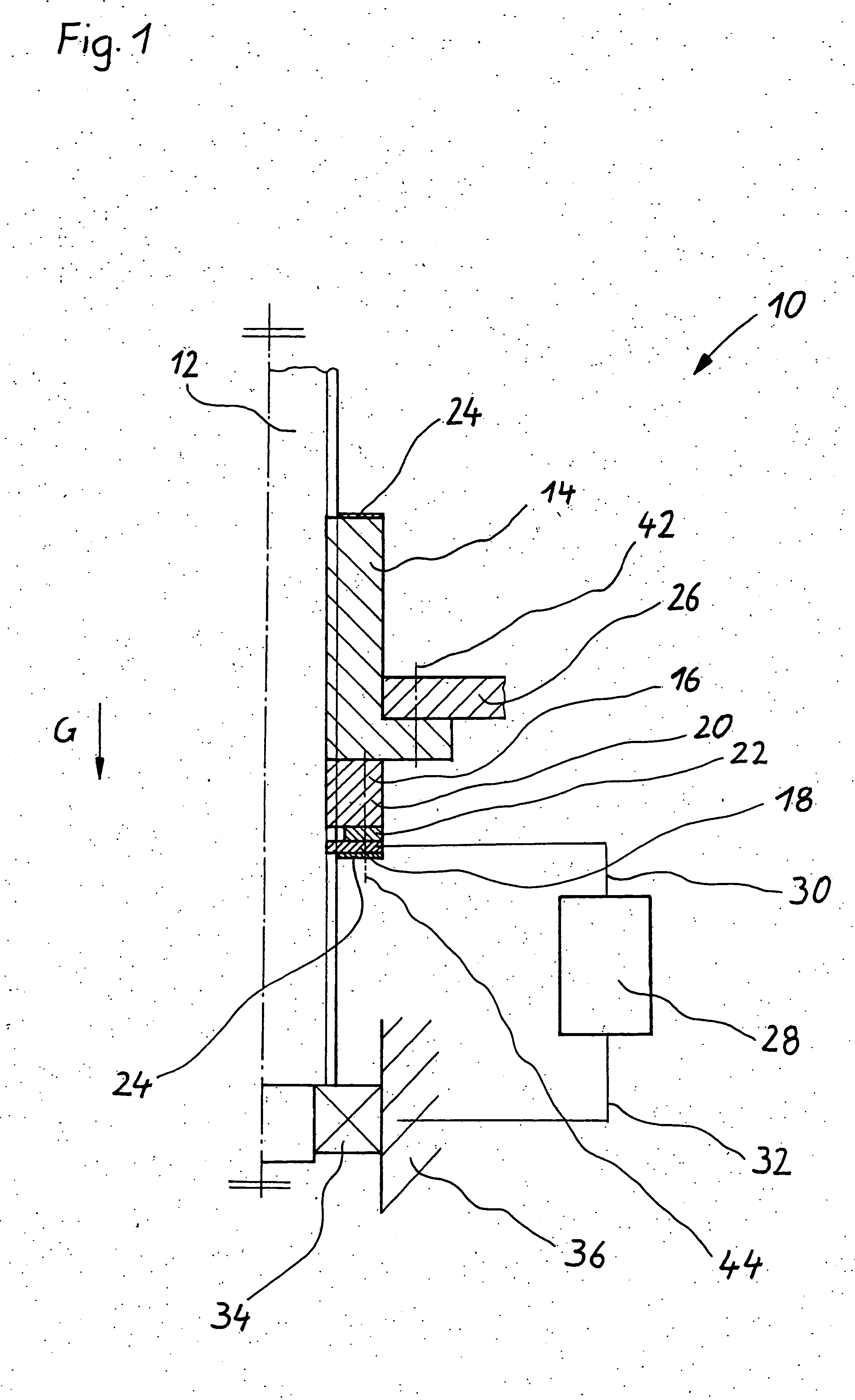
[0018] In FIG. 1, a thread drive of the invention is identified overall by reference numeral 10. The thread drive comprises a threaded spindle 12, a load-bearing nut 14, and a safety nut 16. The threaded spindle is supported rotatably in a stationary bearing housing 36 by a bearing 34, which is embodied as a radial deep-groove ball bearing. The load-bearing nut 14, which is embodied as a ball race nut, is secured by screw bolts 42, shown in simplified form, to a higher-order component unit 26, which is supported counter to the direction of gravity G by the thread drive 10.

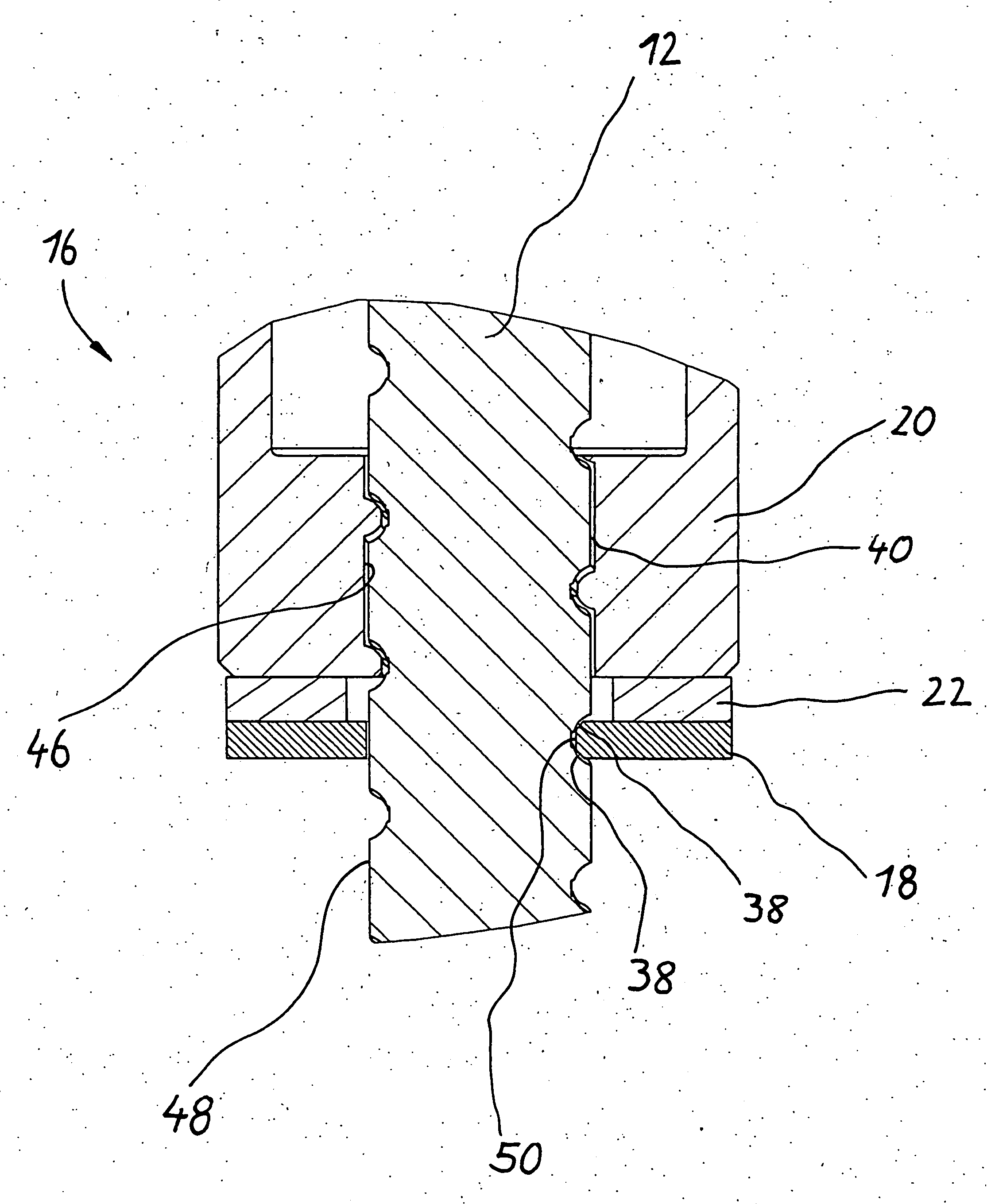
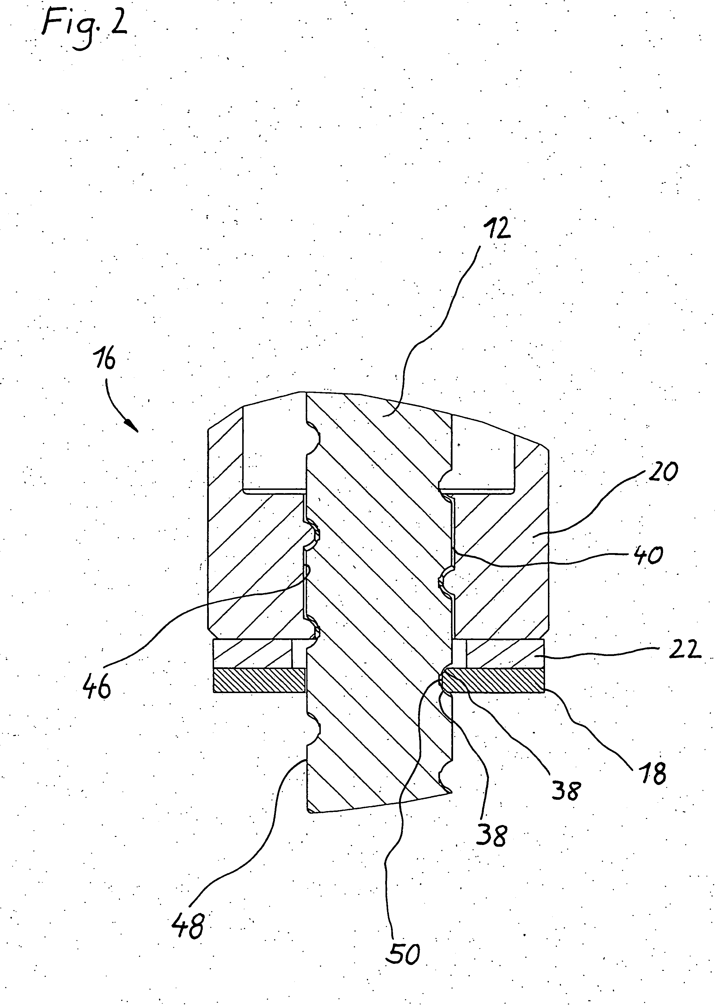
[0019] The safety nut 16, which is shown in more detail in FIG. 2, comprises a load-bearing portion 20 and a contact portion 18. The load-bearing portion and the contact portion are electrically insulated from one another by an electrically nonconductive component 22. The safety nut 16 is secured by screw bolts 44, also shown in simplified form, to the load-bearing nut in a manner fixed against relative rotation. ...


PUM


Abstract

A thread drive has a threaded spindle, a load-bearing nut that is in screwing engagement with the threaded spindle, a safety nut connected to the load-bearing nut in a manner fixed against relative rotation, which is likewise in screwing engagement with the threaded spindle, the safety nut having at least one contact portion which has no contact with the threaded spindle in a first operating state of the thread drive and has contact with the threaded spindle in a second operating mode of the thread drive, so that in the first operating state there is no electrically conductive connection between the at least one contact portion of the safety nut and the threaded spindle.

Description

CROSS-REFERENCE TO A RELATED APPLICATION [0001] The invention described and claimed hereinbelow is also described in German patent application DE 10 2005 017 429.9 filed on Apr. 15, 2005. This German patent application, whose subject matter is incorporated here by reference, provides the basis for a claim of priority of invention under 35 U.SC. 119(a)-(d). BACKGROUND OF THE INVENTION [0002] The present invention relates to a thread drive. More particularly, it relates to a thread drive with a monitoring safety nut. [0003] One such thread drive is known from German Patent DE 196 25 999 C2, for instance. There, in FIG. 1, a thread drive 10 with a threaded spindle 12, a load-bearing nut 14 and a safety nut 18 is shown. The load-bearing nut and safety nut are connected to one another in a manner fixed against relative rotation and are each in screwing engagement with the threaded spindle. In a first operating state, namely the normal operating mode of the thread drive, only the load-bea...

Claims


Application Information

Patent Timeline
Patent Type & Authority Applications(United States)
IPC IPC(8): F16H27/02
CPCY10T74/18576F16H25/2472
Inventor KLEIN, MICHAELSCHLERETH, RUDOLFGREUBEL, ROLANDBLAUROCK, WERNER
Owner BOSCH REXROTH MECHATRONICS
Why Eureka
Try Eureka