Power-supplying member and heating apparatus using the same

a technology of power supply member and heating apparatus, which is applied in the direction of ohmic-resistance heating, hot plate heating arrangement, coating, etc., can solve the problems of large difference between the thermal expansion amount the tubular supporting member, excessive stress, critical cracks in the ceramic base in the vicinity of the joint part, etc., to achieve the effect of improving the reliability of the heating apparatus, facilitating buckles, and maintaining the hardness of the power supply member

Active Publication Date: 2006-10-19
NGK INSULATORS LTD
View PDF3 Cites 12 Cited by
  • Summary
  • Abstract
  • Description
  • Claims
  • Application Information

AI Technical Summary

Benefits of technology

[0011] According to the present invention, as shrink properties can be given to power-supplying member, the power-supplying member can absorb an amount of change in shape due to its thermal expansion by shrink of the thermal-expansion absorbing member, even in a case where power supply generates heat on the power-supplying member, and thus the power-supplying member thermally expands, while the power-supplying member is connected to the power supplied object. Accordingly, the power-supplying member of the present invention makes it possible to improve reliability of the heating apparatus.
[0012] It is desirable that the thermal-expansion absorbing member is a member formed in any one of a structure spiraling a rod-shaped member, a structure spiraling a thin-plate member, and a structure which the thin-plate member has alternating series of convex and concave bending portion in the longitudinal direction, each bending portion extending along a direction orthogonal to the longitudinal direction. According to such a structure, as spring properties can be given to the thermal-expansion absorbing member, the thermal-expansion absorbing member can adequately shrink in response to thermal expansion. Accordingly, it is possible to absorb an amount of change in shape of the power-supplying member due to its thermal expansion.
[0013] The thermal expansion absorbing member may include a curved portion. According to such a structure, the power-supplying member can be provided with a structure having spring properties or a structure capable of causing the thermal-expansion absorbing member to easily buckle, while maintaining the hardness of the power-supplying member as a whole without necessitating change in the cross-sectional form of the thermal-expansion absorbing member. As a result, the thermal-expansion absorbing member can adequately shrink or buckle in response to change in shape due to its thermal expansion. Accordingly, this makes it possible to absorb an amount of change in shape of the power-supplying member due to the thermal expansion.
[0014] It is desirable that the thermal-expansion absorbing member is formed from a member which Young's modulus is 50 [Gpa] or more smaller then Young's modulus of the first and second rod-shaped member. According to such a structure, the thermal-expansion absorbing member can shrink more easily and can adequately shrink in response to cleanse in shape due to its thermal expansion thermal expansion. As a result, this makes it possible to absorb an amount of change in shape of the power-supplying member due to the thermal expansion.

Problems solved by technology

This brings about a problem that the difference between the power-supplying member and the tubular supporting member in amount of thermal expansion is large.
For this reason, according to the ceramic heaters of the related art, as the power-supplying member cannot freely expand thermally in response to temperature change, excessive stress occurs in a joint part where the heating resistor or the electrode is joined to the power-supplying member.
The occurrence of the stress brings about a problem that the stress disconnects a power-supplying member from the heating resistor or the electrode (terminal disconnection), and a problem that the stress causes critical cracks in the ceramic base in the vicinity of the joint part.
Accordingly, the ceramic heaters of the related art have a problem in reliability.

Method used


Image

  • Power-supplying member and heating apparatus using the same
  • Power-supplying member and heating apparatus using the same
  • Power-supplying member and heating apparatus using the same

Examples


first embodiment

(Configuration of Power-Supplying Member)

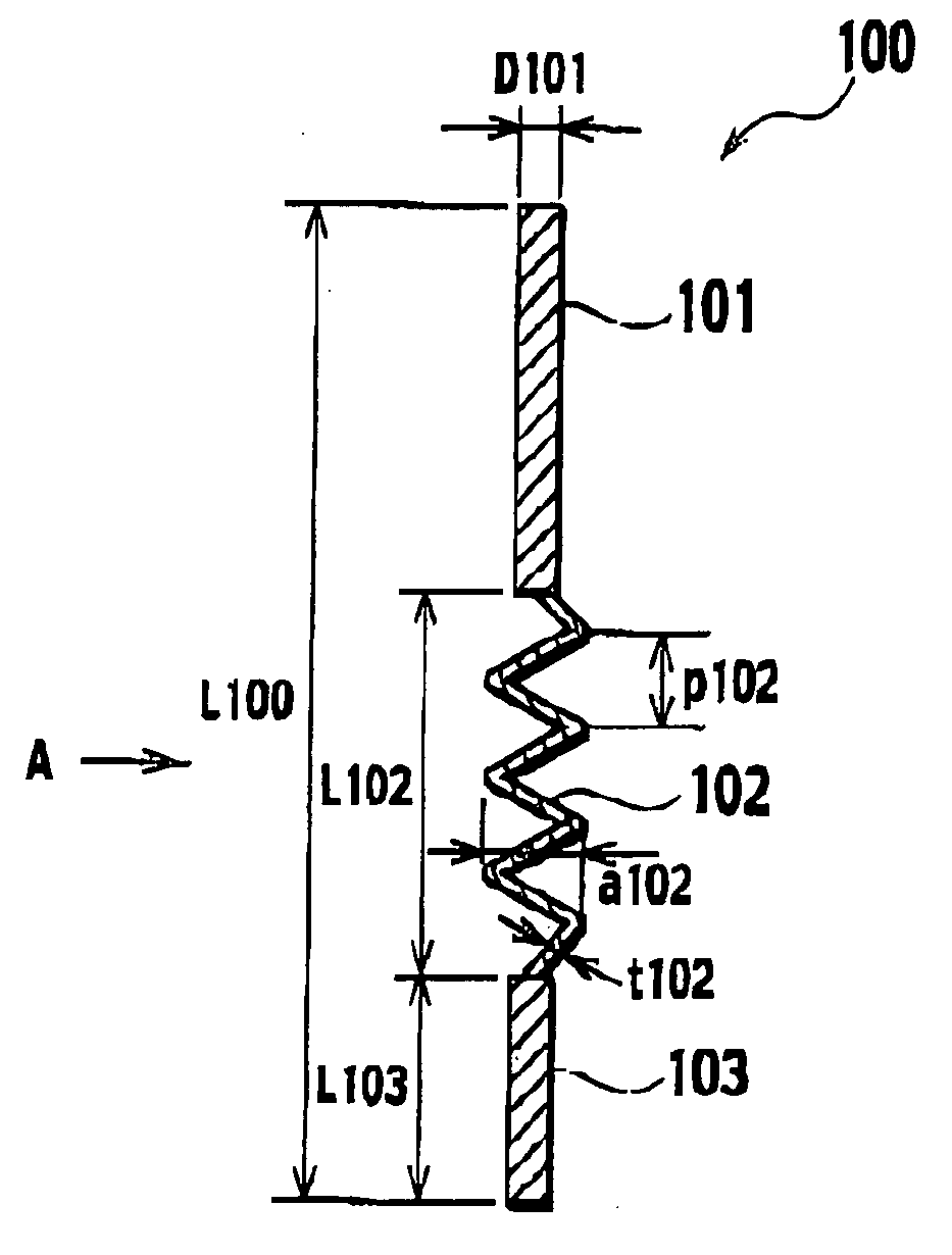
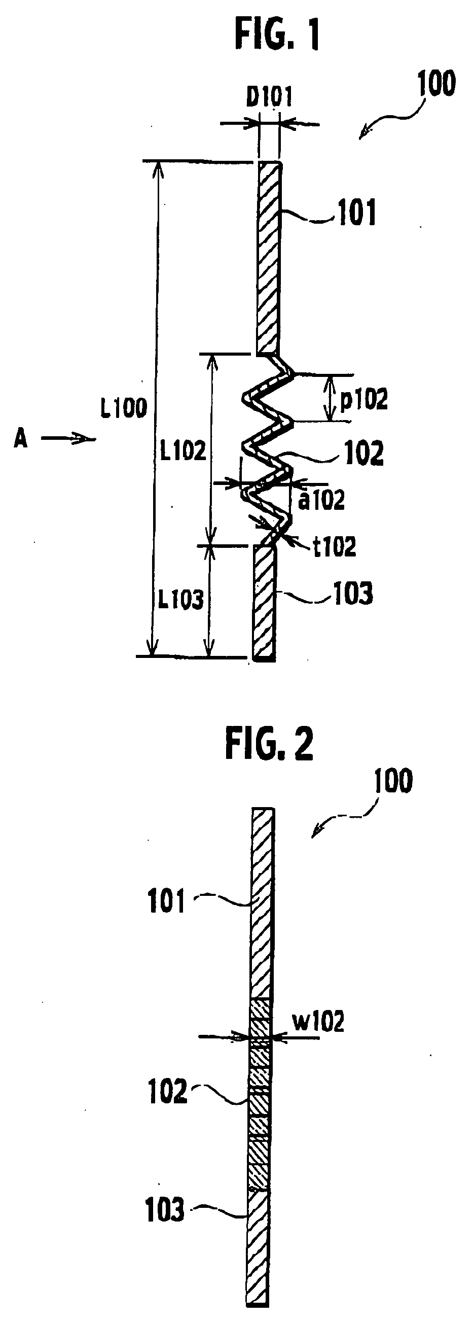
[0028] Descriptions will be provided for a power-supplying member according to first embodiment of the present invention with reference to FIGS. 1 and 2. FIG. 1 shows a side view of the power-supplying member, and FIG. 2 shows a side view of the power-supplying member in the case the power-supplying member is viewed from direction A shown in FIG. 1.

[0029] The power-supplying member 100 according to first embodiment is disputed to a hollowed part in a tubular supporting member. A heating resistor and an electrode are embedded in a ceramic base to be supported by the supporting member. The power-supplying member 100 supplies power to at least one of the heating resistor and the electrode as power-supplied object. As shown in FIGS. 1 and 2, the power-supplying member 100 includes a first rod-shaped member 101, a second rod-shaped member 103 and a thermal-expansion absorbing member 102. The first rod-shaped member 101 is connected to the power...

second embodiment

(Configuration of Power-Supplying Member)

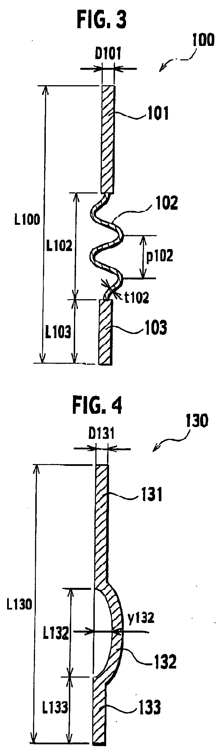
[0042] Hereinafter, descriptions will be provided for a power-supplying member according to a second embodiment of the present invention with reference to FIG. 4. The following descriptions will focus mainly on what makes the Second embodiment different from the first embodiment.

[0043] In the case of the second embodiment, as shown in FIG. 4, a thermal-expansion absorbing member 132 is provided with a curved portion having a amount of bend y132 which is not smaller than 0.1 [mm]. The amount of bend y132 means the distance from the centerline of a first rod-shaped member 131 and a second rod-shaped member 133 in the longitudinal direction to the thermal-expansion absorbing member 132. The thermal-expansion absorbing member 132 is not shorter than 3 [mm] in length L132 in the longitudinal direction. When necessity for maintaining a certain level of hardness of the power-supplying member 130 is taken into consideration, it in desirable that t...

third embodiment

(Configuration of Power-Supplying Member)

[0047] Hereinafter, descriptions will be provided for a power-supplying member according to a third embodiment of the present invention with reference to FIG. 5. The following descriptions will focus mainly on what makes the third embodiment different from the first embodiment.

[0048] In the case of the third embodiment, the thermal-expansion absorbing member 152 is formed from a member haying a Young's modulus which is not 50 [Gpa] or more larger than a Young's modulus of a first rod-shaped member 151 and a second rod-shaped member 153. Specific combination examples of members are described in the following examples. The length L152 of the thermal-expansion absorbing member 152 is not shorter than 0.1 [mm], but not longer than 50 [mm]. For the purpose of maintaining the hardness of the power-supplying member 150, however, it is more desirable that the length L152 should be not shorter than 0.3 [mm], but not longer than 30 [mm].

(Method of...


PUM

PropertyMeasurementUnit
electric currentaaaaaaaaaa
diameter D101aaaaaaaaaa

Abstract

A power-supplying member comprises: a first rod-shaped member connected to power-supplied object; a second rod-shaped member connected to power supply; and a thermal-expansion absorbing member, which is disposed between the first rod-shaped member and the second rod-shaped member, and which shrinks in a longitudinal direction in response to changes in shape of the first rod-shaped member and the second rod-shaped member in the longitudinal direction due to thermal expansion.

Description

CROSS REFERENCE TO RELATED APPLICATIONS [0001] This application is based upon and claims the benefit of priority from provisional application 60 / 672,737 filed on Apr. 19, 2005, and Japanese patent application No. Tokugan 2006-111542 filed on Apr. 14, 2006; the entire contents of which are incorporated by reference herein.BACKGROUND OF THE INVENTION [0002] 1. Field of the Invention [0003] The present invention relates to a power-supplying member and a heating apparatus using the same, suitable for semiconductor manufacturing systems such as thermal chemical Vapor Deposition (CVD) systems and plasma CVD systems. [0004] 2. Description of the Related Art [0005] There is conventionally known, as disclosed in Japanese Patent Application Laid-Open No. HS-326112, heating apparatuses (hereinafter referred to as “ceramic heaters”) comprise a ceramic base in which a heating resistor oz an electrode are embedded a tubular supporting member which supports the ceramic base; and a power-supplying ...

Claims


Application Information

Patent Timeline
Patent Type & Authority Applications(United States)
IPC IPC(8): C23C16/00H05B3/16
CPCH01L21/67103H05B3/143H01L21/68757
Inventor GOTO, YOSHINOBUTSURUTA, HIDEYOSHI
Owner NGK INSULATORS LTD
Why Eureka
Try Eureka