Seat slide apparatus

a technology of seat slide and seat rail, which is applied in the direction of movable seats, machine supports, other domestic objects, etc., can solve the problems of obstructing the path of getting, passenger workload, and difficulty in fitting the lead screw & nut or the “rack & pinion” in full length of the long rail with high precision

Inactive Publication Date: 2006-10-19
HONDA MOTOR CO LTD +1
View PDF5 Cites 13 Cited by
  • Summary
  • Abstract
  • Description
  • Claims
  • Application Information

AI Technical Summary

Problems solved by technology

However, when passengers get on the third row seats, the seat disposed immediately before these seats (referred to as “second row seat”) obstructs the path for getting on and off.
Since the long rail has a wide movable range, when a passenger slides the seat on the long rail in a wide range by hand (manual operation), the passenger suffers a workload.
Therefore, it is difficult to fit the “lead screw & nut” or “rack & pinion” in full length of the long rail with high precision.
Also, in the case where a system of the “lead screw & nut” or the “rack & pinion” is employed and when the driving speed is increased, large noises and vibrations maybe generated resulting in an uncomfortable feeling to the passengers.
However, there resides a problem in the technique disclosed in the Japanese Patent Application Laid-Open No. 2004-243811 such that, irrespective of the situation whether the seat is in a walk-in operation or in an ordinary front / rear position adjustment, the upper rail member has to has a constitution to be always slid (moved) at a constant speed.
When the walk-in function is activated and the seat is made to slide a long distance under such speed setting, the sliding movement is felt to be too slow.
In this case, there arises such a problem that various control devices are additionally required resulting in an increase of manufacturing process and cost.
Further, there arises such a problem that the risk of trouble is increased due to the complicated apparatus itself.
Further, in the technique disclosed in the Japanese Patent Application Laid-Open No. 2004-243811, there resides such a problem that, irrespective of the situation whether the seat is in a walk-in operation or in an ordinary front / rear position adjustment, the seat has to have a constitution to be always slid by a driving force (motor).
This inevitably leads to such a problem that the weight and cost of the apparatus itself is increased.
Furthermore, in the case where the seat is made to slide using a power drive unit in a state passengers sit on the seat, there resides such a problem to the sliding speed of the seat has to be controlled to a low speed in order to ensure the safety of the passenger and to obtain a satisfactory torque of the motor.

Method used


Image

  • Seat slide apparatus
  • Seat slide apparatus
  • Seat slide apparatus

Examples


Embodiment Construction

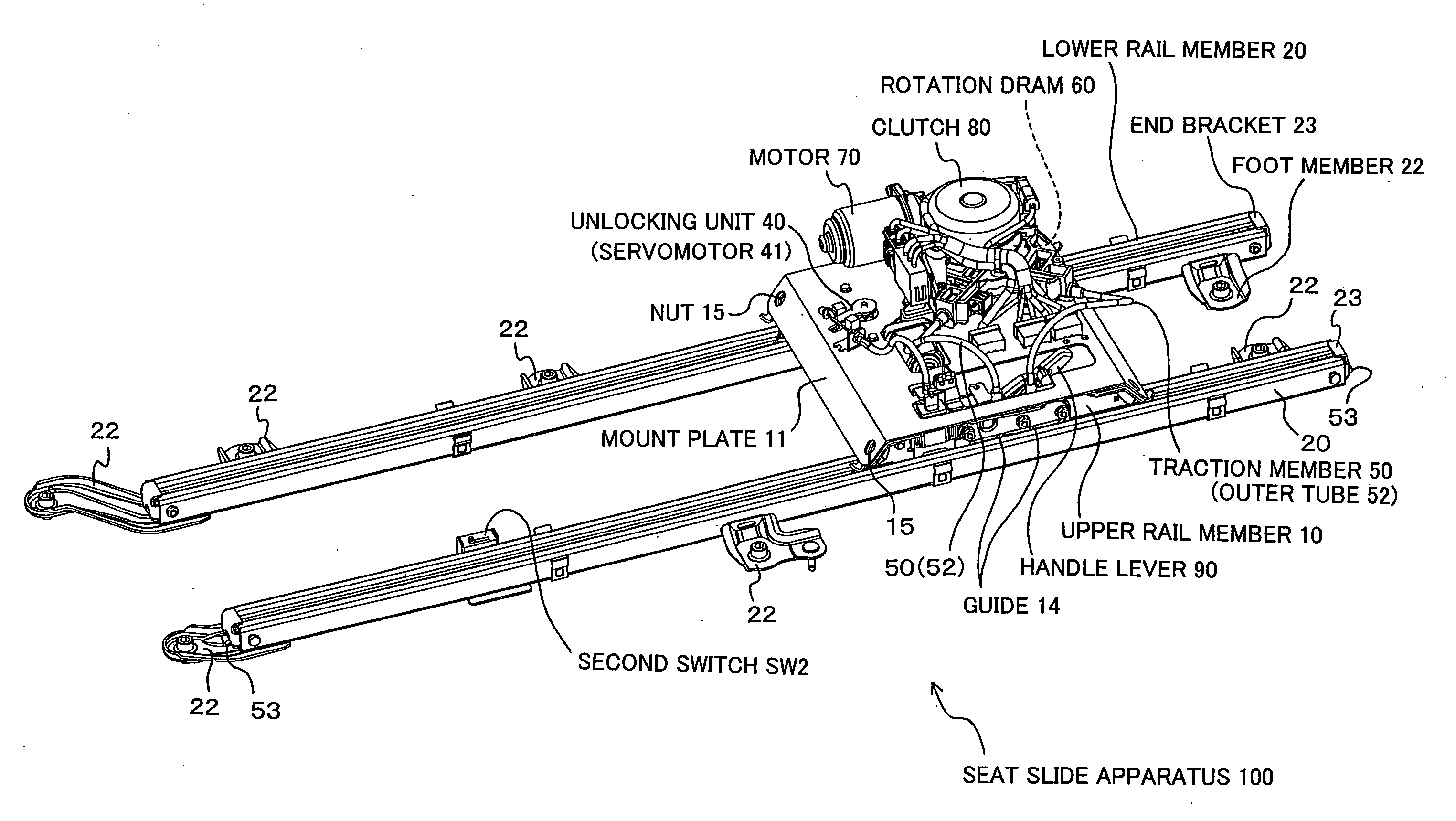
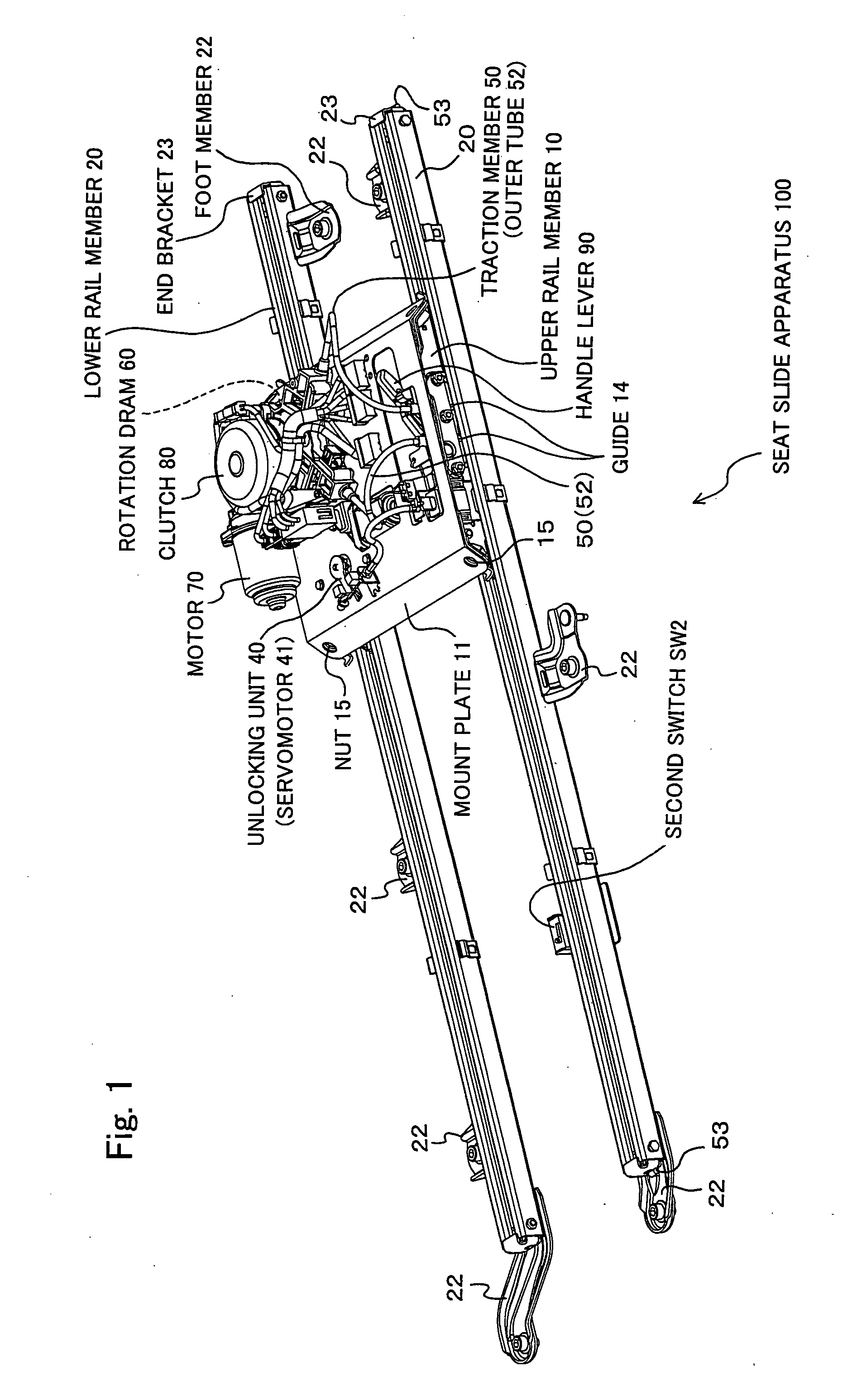
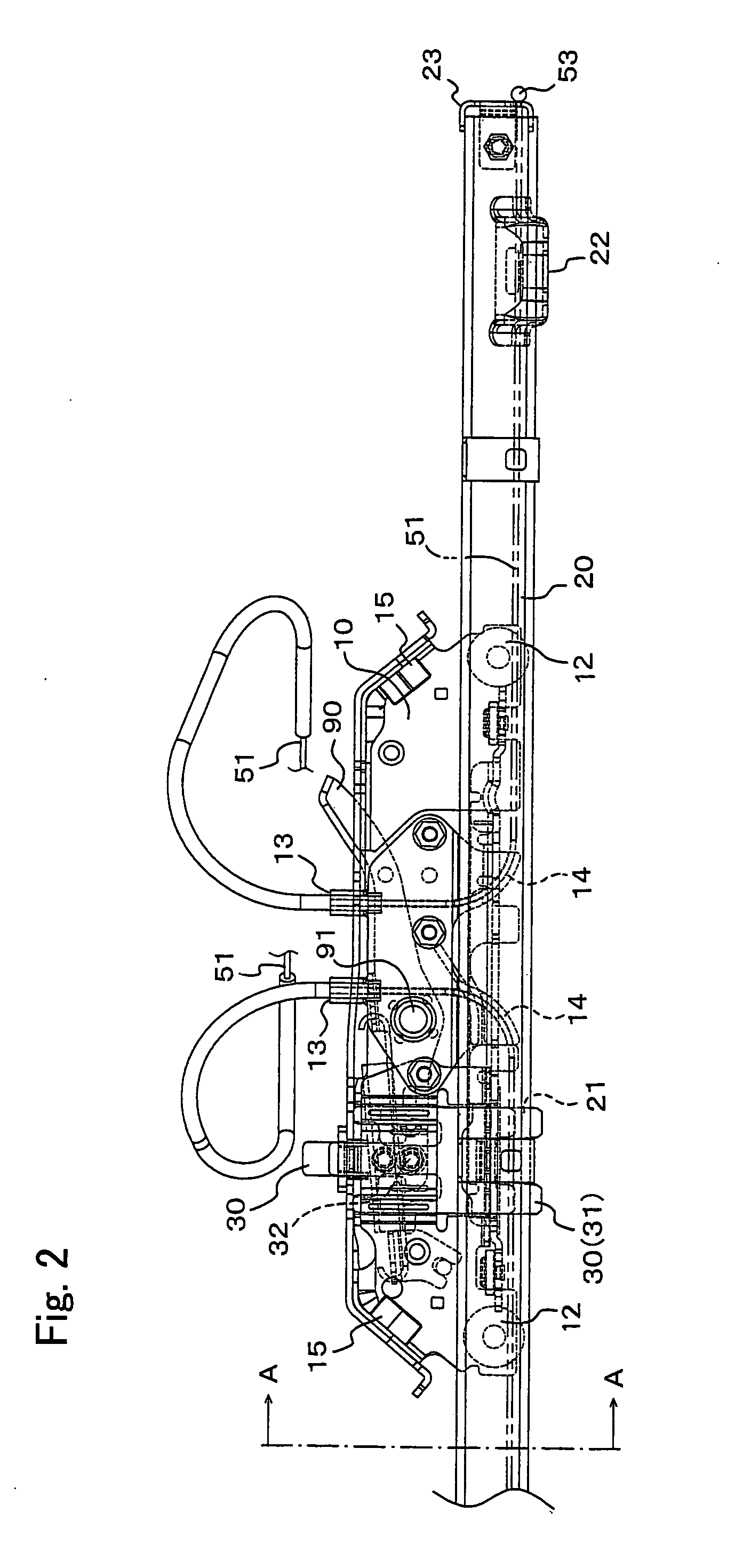
[0032] First, a seat slide apparatus 100 includes an upper rail member 10 capable of mounting a seat cushion; a lower rail member 20 capable of being firmly fixed to a floor face of a vehicle; a locking unit 30 disposed to the upper rail member 10 for locking and unlocking relative movement of the upper rail member 10 with respect to the lower rail member 20; an operation lever 90 connected to the locking unit 30 capable of being manually operated to lock and unlock the locking unit 30 by a passenger; a unlocking device 40 connected to the locking unit 30 for locking and unlocking the locking unit 30 using a power; a traction member 50 for pulling the upper rail member 10, of which both ends are connected to the front and the rear ends of the lower rail member 20; a rotation drum 60 disposed on the rear side of the upper rail member 10 or seat cushion for winding the traction member 50; a motor 70 connected to a rotation drum 60 for rotating the rotation drum 60; clutch 80 for trans...


PUM


Abstract

A simply structured and inexpensive seat slide apparatus, which, in an ordinary front/rear position adjustment of a seat, allows a passenger to operate manually without using a power drive unit; and in walk-in operation only, enables the seat to slide swiftly using the power drive unit.

Description

CROSS REFERENCE TO RELATED APPLICATION [0001] The present invention claims priority under 35 U.S.C. §119 to Japanese Application No. 2005-016595 filed Jan. 25, 2005, which is incorporated herein by reference. FIELD OF INVENTION [0002] The present invention relates to a seat slide apparatus having a lower rail member firmly fixed to a floor face of a vehicle and an upper rail member mounted with a seat cushion, which is capable of adjusting the position of a seat for the vehicle forward and backward, in particular to a seat slide apparatus arranged so that the upper rail member and the lower rail member are connected to each other via a traction member such as a wire, and by pulling the traction member with a power unit, the upper rail member can be slid on the lower rail member. BACKGROUND [0003] In one-box type vehicles represented by “minivan” or “cab wagon”, many types of vehicles are equipped with three row seats in the interior. With respect to a seat disposed in the third row,...

Claims


Application Information

Patent Timeline
Patent Type & Authority Applications(United States)
IPC IPC(8): F16M13/00
CPCB60N2/0232B60N2/0715B60N2/12B60N2/0881B60N2/0818B60N2/02246
Inventor KAYUMI, TETSUYASUDA, HIROHIDEMORI, AKINORIMITSUKUCHI, MASASHI
Owner HONDA MOTOR CO LTD
Why Eureka
Try Eureka