
Process for controlling industrial robots, and related robots, systems and computer programs

Active Publication Date: 2006-10-19
COMAU SPA
View PDF7 Cites 9 Cited by
  • Summary
  • Abstract
  • Description
  • Claims
  • Application Information

AI Technical Summary

Benefits of technology

[0009] In the light of the above, the present invention aims at implementing an industrial robot as previously referred to, ensuring an improved level of safety as far as programming activity is concerned, and whose manufacture is simple, cheap and reliable. The invention further aims at implementing a robot as previously referred to which enables an easy and versatile activity involving programming and manual control by means of a portable terminal, however under fully safe conditions.

Problems solved by technology

The aforesaid cable enables a limited controllability for the operator in his / her programming activity, since s / he should move continuously near the manipulator; another drawback consists in that the cable can get caught or entangled with other cables and should thus be freed.
Moreover, the cable is subject to wear and tear and damages and therefore needs to be repaired or replaced.
The solution mentioned above complicates to a certain extent the implementation of the portable terminal, which should be equipped with a suitable seat and with related means of physical interconnection for the removable module; removable modules are further subject to frequent handlings, which might engender confusions as well as damages and a rapid wear and tear of their contacts, with subsequent risks of bad working.

Method used


Image

  • Process for controlling industrial robots, and related robots, systems and computer programs
  • Process for controlling industrial robots, and related robots, systems and computer programs
  • Process for controlling industrial robots, and related robots, systems and computer programs

Examples


Embodiment Construction

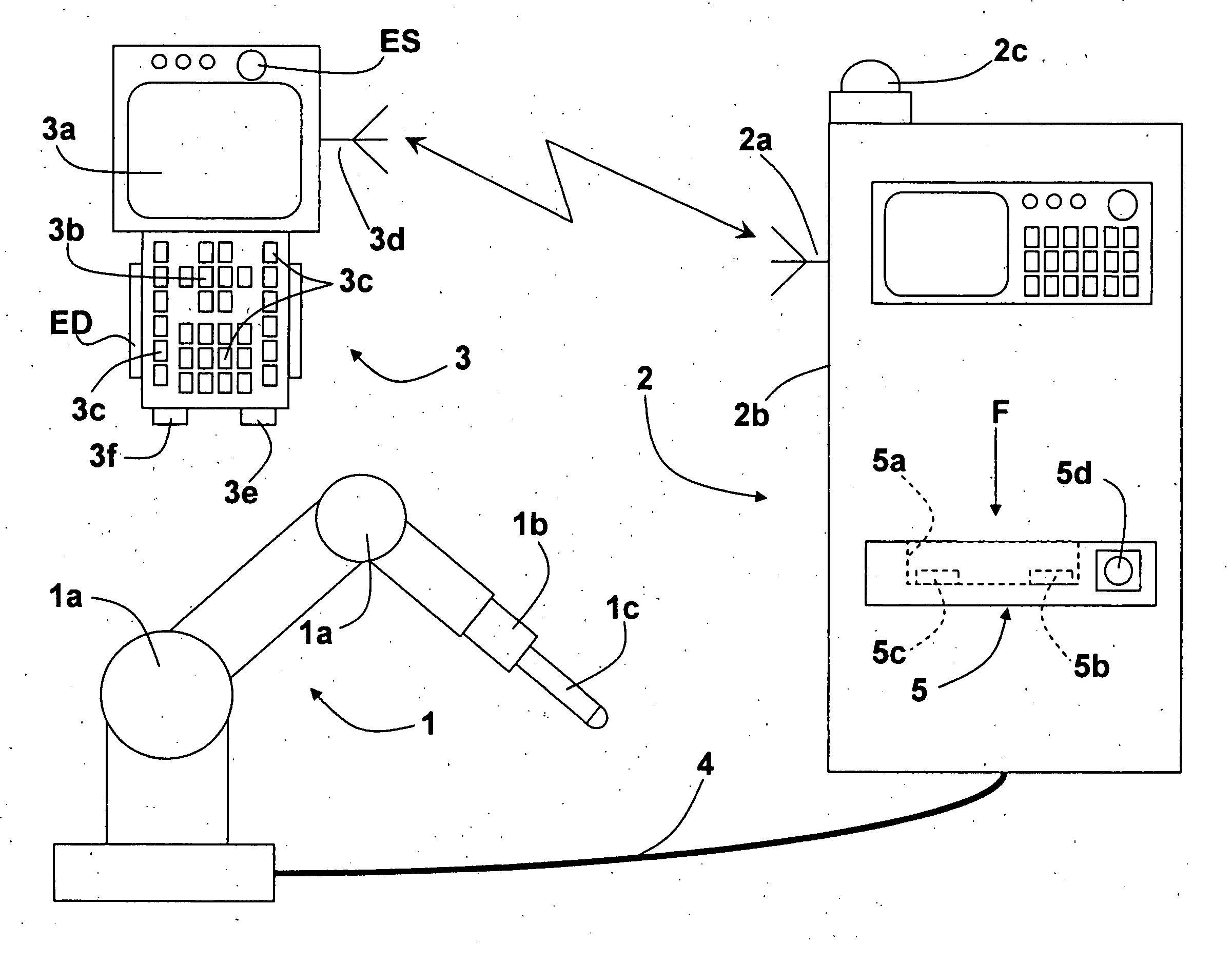
[0019]FIG. 1 shows an industrial robot comprising a manipulator 1, a control unit 2 and a portable programming terminal or teach pendant 3. The manipulator 1 has a plurality of parts moving according to respective axes, articulated by means of joints 1a, and an end wrist 1b carrying a generic tool 1c. The manipulator 1 is connected by means of a cable 4 to its control unit 2. The terminal 3 comprises at least

[0020] a display 3a, by means of which machine statuses, programming steps, possible alarms and various parameters, such as the position of the axes of the manipulator, can be monitored; the display 3a is used both when programming the positions of the axes and the steps of a movement program and as remote monitor for the unit 2;

[0021] a group of keys for controlling the motion of the axes of the manipulator 1, some of which are referred to with 3b; the keys of said groups comprise in particular those for selecting the desired motion reference system and those for controlling ...


PUM


Abstract

An industrial robot includes a manipulator (1) having a control unit (2) and a portable terminal (3), the unit and the terminal being able to communicate in wireless mode for executing a robot programming session. The unit (2) and the terminal (3) are configured so as to implement a step of mutual logic coupling, which is required so as to enable the programming session, only when the terminal (3) is in a substantially predefined physical position (5) close to the unit (2).

Description

BACKGROUND OF THE INVENTION [0001] The present invention relates to industrial robots and was conceived in particular for the possible application of robots with a portable terminal associated therewith and designed to communicate in wireless mode with the robot control unit. [0002]“Wireless” refers here to a communication involving a wireless communication of signals by means of electromagnetic waves, preferably by radio-frequency but possibly also by means of ultrasounds or infrared radiations or radiations in another frequency field. [0003] Programming a robot basically means teaching said robot the trajectory which a point of its manipulator should repeat automatically during normal operating steps in order to execute a given operation. A robot can thus operate at least in an automatic and in a manual mode, which can usually be selected on the robot control unit. When manual mode is selected, for instance for programming or “teaching” a robot, the respective manipulator can be h...

Claims


Application Information

Patent Timeline
IPC IPC(8): G05B19/19
CPCG05B19/42G05B2219/23414G05B2219/33192G05B2219/50198G05B2219/39001G05B2219/39447G05B2219/36159B25J9/042G05B2219/31286
Inventor CALCAGNO, RENZO
Owner COMAU SPA
Learn More