Asynchronous servo RRO detection employing interpolation

a technology of rro detection and asynchronous servo, applied in the direction of maintaining head carrier alignment, amplitude demodulation, instruments, etc., can solve the problems of unfavorable data acquisition and transmission, and inability to accurately read servo information,

Inactive Publication Date: 2006-10-19
AVAGO TECH WIRELESS IP SINGAPORE PTE
View PDF2 Cites 11 Cited by
  • Summary
  • Abstract
  • Description
  • Claims
  • Application Information

AI Technical Summary

Problems solved by technology

Imperfect spindles might not allow the disk in the hard drive to spin properly at the disk's center.
If the disk is not rotating at the center, the track rotating under the head does not follow a circular trajectory, and hence the head might not be able to read the servo information properly.
Even though the disk may spin properly in a different hard disk drive while reading the servo information, since the information was not written properly on a circular track, the head might not be able to read the servo information accurately.
Also, detection of the RRO address mark is prone to detection errors because the RRO detector may begin detection in the DC erase field without proper sampling phase (i.e., there is no preamble to guide the timing loop).
The performance of these detectors degrades significantly when the samples are generated with timing errors.
Since the sampling phase is not known when reading the RRO data field, a Viterbi detector is more prone to making errors.

Method used


Image

  • Asynchronous servo RRO detection employing interpolation
  • Asynchronous servo RRO detection employing interpolation
  • Asynchronous servo RRO detection employing interpolation

Examples


Embodiment Construction

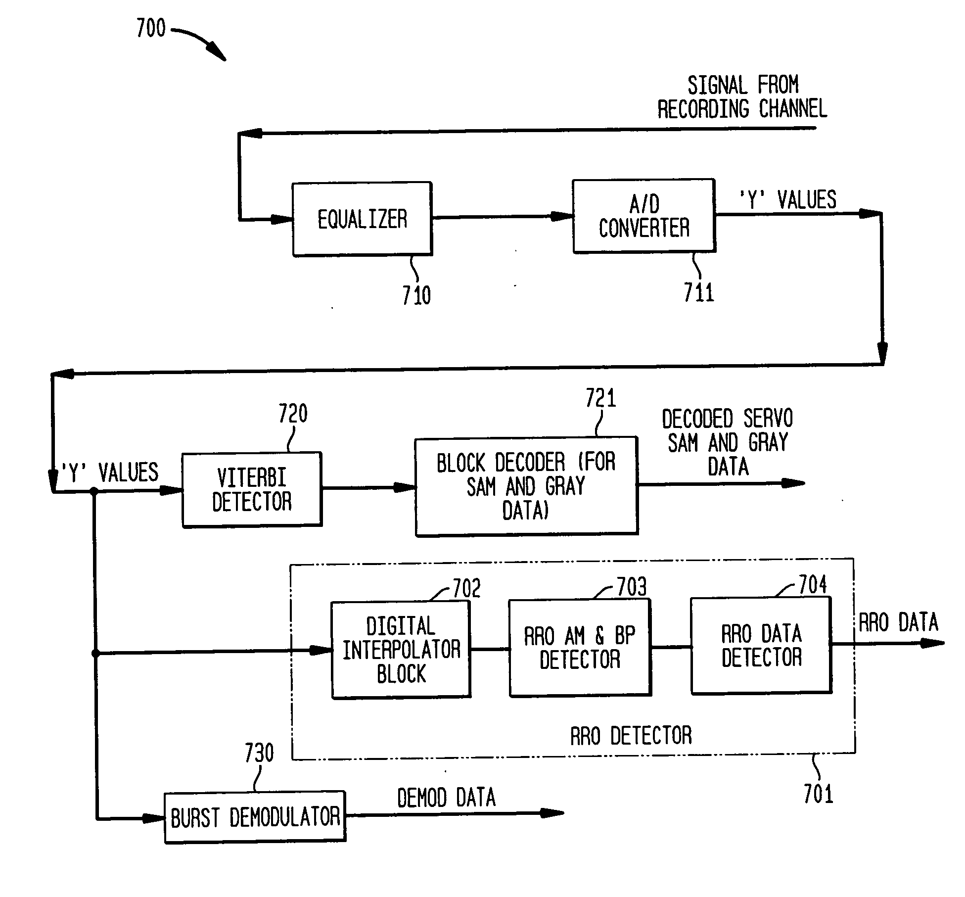
[0037]FIG. 7 shows a receiver 700 including a repeatable run out (RRO) detector 701 for detecting and decoding RRO data in accordance with exemplary embodiments of the present invention. Receiver 700 comprises equalizer 710 and A / D converter 711. Equalizer 710 applies equalization to a signal read from a magnetic recording medium, such as a magnetic recording disk, to compensate for effects of inter-symbol interference (ISI) and signal dispersion caused by the signal's passage through the magnetic recording medium. The analog signal may represent a series of symbols for servo data, such as encoded SAM, Gray, and RRO data as shown in FIGS. 3 and 4. Equalizer 710 may include a switch to enable sampling of the analog signal. A / D converter 711 generates digital samples at a symbol rate T from the equalized signal from equalizer 710. Sampling of the signal from equalizer 710 may be synchronous using the timing information from a digital phase-locked loop (DPLL, not shown in FIG. 7) when ...


PUM

PropertyMeasurementUnit
phaseaaaaaaaaaa
trajectoryaaaaaaaaaa
magnetizationaaaaaaaaaa

Abstract

A repeatable read-out (RRO) detector employs one or more digital interpolators to interpolate asynchronous sample values that represent RRO data. The asynchronous sample values are read from a recording medium and generated by an A / D converter at a symbol rate, and the interpolators generate interpolated samples at at least one time in between the asynchronous sample value times. Each interpolated sample corresponding to some phase relative to that of the sample values generated by the A / D converter. The RRO detector receives 1) the asynchronous samples at symbol rate and 2) the interpolated samples to efficiently detect the encoded RRO data. An RRO address mark indicates when detection of encoded RRO data starts, and is employed to select those samples suitable for RRO data detection. Detection of the RRO address mark employs peak detection among filtered asynchronous and interpolated samples. The process of peak detection adjusts the current best phase for sample selection. When the RRO address mark is found, the corresponding best phase corresponds to either asynchronous sampled values or interpolated samples that are subsequently selected for RRO data detection, termed best samples. Once the best phase is selected, the RRO data detector uses that information along with RRO encoding constraints to decode the encoded RRO data from the best samples.

Description

CROSS-REFERENCE TO RELATED APPLICATION [0001] The present invention is a continuation of co-pending U.S. application Ser. No. 10 / 342,153 filed Jan. 14, 2003.BACKGROUND OF THE INVENTION [0002] 1. Field of the Invention [0003] The present invention relates to detection of data in a communications system, and, more particularly, to detection of servo repeatable run out (RRO) information from a channel. [0004] 2. Description of the Related Art [0005] A Read channel integrated circuit (IC) is a component of a modem hard disk drive, such as a hard disk drive found in many PCs. A Read channel component converts and encodes data to enable the (e.g., magnetic) recording head(s) to write data to the disk drive and then read back the data accurately. The disks in a drive typically include many tracks containing encoded data, and each track comprises one or more of user (or “read”) data sectors as well as “servo” data sectors embedded between the read sectors. The information of the servo secto...

Claims


Application Information

Patent Timeline
Patent Type & Authority Applications(United States)
IPC IPC(8): H04L27/06G11B5/596
CPCG11B5/59627
Inventor ANNAMPEDU, VISWANATHAZIZ, PERVEZ M.
Owner AVAGO TECH WIRELESS IP SINGAPORE PTE
Why Eureka
Try Eureka